Message from David McBean
IMPORTANT UPDATE - HORNRESP VERSION 21.10
Hi Everyone,
Yesterday I discovered that the input data validation and error-handling routines that had worked so well in the Visual Basic 3 implementation of Hornresp (and also in the Visual Basic 6 development environment) produced somewhat different results when compiled into the VB6 production version of the program.
This rather serious inconsistency was caused by a problem with Visual Basic 6 itself, rather than being due to any coding bug in the program. As a matter of urgency though, I have changed the routines so that Hornresp again now operates as it should.
I strongly recommend that you upgrade to the new release. Sorry for any inconvenience caused by the incorrect operation of the old VB6 input validation routines.
Could you please spread the word regarding the new Hornresp release via any other Forums that you might visit. Many thanks.
Kind regards,
David
My latest project
A little progress report on my latest project.
This is a home-theater sub designed with 4 Tang-Band W6-1139s. If all goes as planned, it will replace a Velodyne ULD-12. (If things do not go as planned, it is because I did not translate what I modeled in hornresp to what I actually built!)
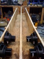
I had a serious space constraint to meet, and even this enclosure is a compromise there. Externally, it is 8.5 by 19 by 77 inches - so it is not a small box. The little Tang-Band drivers have a surprisingly large mounting depth, which eliminated several of the other folding options. In retrospect, I'd certainly do some things differently, but before I start with the armchair quarterbacking, I need to finish this one and see how well it actually works first.
It is a simple up-back fold with a small ported compression chamber. I've also split the horn throats to make things fit together better and minimize the length of the row of drivers with respect to the horn. Total length is about 4 meters, so it will work well to 30 Hz. With 4 drivers series-parallel, I'm looking at a 4 ohm sub with an efficiency of 96 dB/2.83 V/2pi. This sub will be corner loaded (against poured concrete sub-grade walls) when installed, which puts me over 105 dB.
The enclosure is made of OSB - another experiment for me based on things I have learned here. I used 3/4" nominal high-resin OSB - Weyerhaeuser's "Gold Edge". It is cheap, void-free, relatively stiff, and it is flat. The imported "hardwood" plywood from Home Depot that I have used in the past is cheap, but fails at the rest of these things. Brad nails and PL premium construction adhesive hold things together, with a strategic screw or two holding things in place until the glue sets.
I've also added some corner wedges. I know that physics says they don't matter, but it did not take that much additional effort and according to the physics, they should not hurt things either. I've not got the outer sides on it yet, hope to complete the rest of the enclosure this weekend.
Once things are done, I'll measure what I've built and post my measurements and model parameters for discussion.
Here is a pic of the work in progress and my really messy shop.
A little progress report on my latest project.
This is a home-theater sub designed with 4 Tang-Band W6-1139s. If all goes as planned, it will replace a Velodyne ULD-12. (If things do not go as planned, it is because I did not translate what I modeled in hornresp to what I actually built!)
I had a serious space constraint to meet, and even this enclosure is a compromise there. Externally, it is 8.5 by 19 by 77 inches - so it is not a small box. The little Tang-Band drivers have a surprisingly large mounting depth, which eliminated several of the other folding options. In retrospect, I'd certainly do some things differently, but before I start with the armchair quarterbacking, I need to finish this one and see how well it actually works first.
It is a simple up-back fold with a small ported compression chamber. I've also split the horn throats to make things fit together better and minimize the length of the row of drivers with respect to the horn. Total length is about 4 meters, so it will work well to 30 Hz. With 4 drivers series-parallel, I'm looking at a 4 ohm sub with an efficiency of 96 dB/2.83 V/2pi. This sub will be corner loaded (against poured concrete sub-grade walls) when installed, which puts me over 105 dB.
The enclosure is made of OSB - another experiment for me based on things I have learned here. I used 3/4" nominal high-resin OSB - Weyerhaeuser's "Gold Edge". It is cheap, void-free, relatively stiff, and it is flat. The imported "hardwood" plywood from Home Depot that I have used in the past is cheap, but fails at the rest of these things. Brad nails and PL premium construction adhesive hold things together, with a strategic screw or two holding things in place until the glue sets.
I've also added some corner wedges. I know that physics says they don't matter, but it did not take that much additional effort and according to the physics, they should not hurt things either. I've not got the outer sides on it yet, hope to complete the rest of the enclosure this weekend.
Once things are done, I'll measure what I've built and post my measurements and model parameters for discussion.
Here is a pic of the work in progress and my really messy shop.
Attachments
carpenter said:Does the sound wave simply leave the far end?
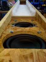
No, I don't think the sides are on yet. It should go down to the far end, turn around and come all the way back and exit at the bottom of the pic.
Littlemike, I'm very interested in the details. My own design is still pending for various reasons... (still working on it though) And as you know I'm designing around the same drivers.
One of the design specifics I've been struggling with is tuning, I wanted 30 hz to keep size and weight ultra portable, but have decided to tune lower for a couple of reasons.
1. I couldn't get the frequency response curve the way I wanted it with a 30 hz tuning.
2. Heat vs xmax. In other words, these little drivers have so much excursion capability they will burn way before they hit bottom unless (and maybe even if) tuned fairly low.
To add to point #2, these drivers are pretty impressive compared to what I'm used to. They are very well vented and therefore very quiet at high excursion. To break one of them in for t/s testing I fed it 10 hz with enough power to visibly deform the surround and then backed off just a bit. (Apparently there's no bottom to hit until you rip the surround off.) 10 minutes of 10 hz gets the driver so hot that it's uncomfortable to hold on to and the smell of hot adhesives fills the room.
So that's 10 minutes at 10 hz at or below it's rated music (not peak) power limit with no box or baffle of any kind. Granted, not much music has continuous 10 hz tones, and granted I was probably somewhere between xmax and xmech during this excapade, but my conclusion is that unless tuned lower than 30 hz as I originally planned, the drivers would burn well before they hit bottom.
Anyway, as my design takes shape I'm very interested in your project details.
@ Carpenter
The sides are not on the cabinet in the photo I attached. The throats are on the outsides, the mouth is in the middle, with the baskets of the drivers hanging in it. Sound will radiate out the end of the enclosure (foreground of the picture). More pictures and measurements to come, as well as the modeling information.
@ just a guy
Details, measurements, and models will come - figured I'd better practice what I've preached by making some sawdust and measuring the results. I've been so busy with other things that this project has taken considerably longer than I initially planned. (Don't they all???)
I agree that these drivers are impressive. I was pushing all my BASH 500W amp could deliver (I measured over 46 volts at 25 Hz) into 4 drivers wired series parallel. There was little to no vent noise even with excursions approaching 3/4" peak to peak. While the drivers got a bit warm, the amp got a lot warmer (and shut off...).
Though my testing has been pretty limited so far, I have not bottomed out one of these drivers. I'd worry most about burning up the voice coils. I have killed other drivers during testing by feeding them high power sine waves. There was no warning that disaster was imminent until the the noise got a lot quieter and the magic smoke came out. Thermal limits are definitely a bigger concern for me than excursion (hence the motors pointing into the mouth).
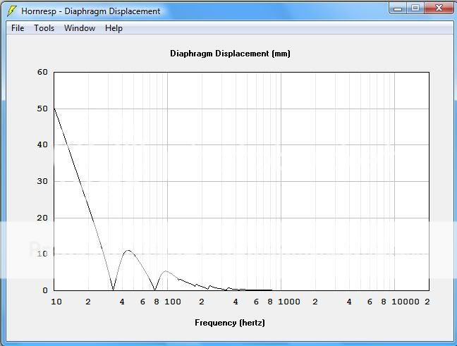
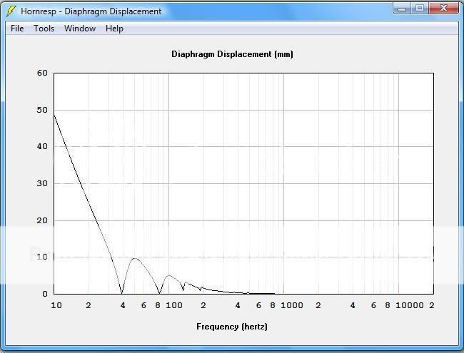
According to Hornresp, the drivers will not exceed xmax in this design unless played below 30 Hz at very high power levels. Within the band of interest (30-120 Hz), excursion peaks at 40 Hz. With 500 watts (125 per driver) applied at 40 Hz, excursion is only 12 mm per driver, still within Xmax. With 100 watts into this cabinet (25 per driver) corner loaded as described earlier, the in room SPL would be 120 dB or more and the excursion is less than half of the xmax of the driver. This is probably a safe limit and realistic expectation, as I am sure there will be power compression effects once more than 50 watts or so is applied per driver.
If these drivers work as well as predicted, I'm going to be really glad that I picked up a pile of them when they were on sale and shipping was free.....
The sides are not on the cabinet in the photo I attached. The throats are on the outsides, the mouth is in the middle, with the baskets of the drivers hanging in it. Sound will radiate out the end of the enclosure (foreground of the picture). More pictures and measurements to come, as well as the modeling information.
@ just a guy
Details, measurements, and models will come - figured I'd better practice what I've preached by making some sawdust and measuring the results. I've been so busy with other things that this project has taken considerably longer than I initially planned. (Don't they all???)
I agree that these drivers are impressive. I was pushing all my BASH 500W amp could deliver (I measured over 46 volts at 25 Hz) into 4 drivers wired series parallel. There was little to no vent noise even with excursions approaching 3/4" peak to peak. While the drivers got a bit warm, the amp got a lot warmer (and shut off...).
Though my testing has been pretty limited so far, I have not bottomed out one of these drivers. I'd worry most about burning up the voice coils. I have killed other drivers during testing by feeding them high power sine waves. There was no warning that disaster was imminent until the the noise got a lot quieter and the magic smoke came out. Thermal limits are definitely a bigger concern for me than excursion (hence the motors pointing into the mouth).
According to Hornresp, the drivers will not exceed xmax in this design unless played below 30 Hz at very high power levels. Within the band of interest (30-120 Hz), excursion peaks at 40 Hz. With 500 watts (125 per driver) applied at 40 Hz, excursion is only 12 mm per driver, still within Xmax. With 100 watts into this cabinet (25 per driver) corner loaded as described earlier, the in room SPL would be 120 dB or more and the excursion is less than half of the xmax of the driver. This is probably a safe limit and realistic expectation, as I am sure there will be power compression effects once more than 50 watts or so is applied per driver.
If these drivers work as well as predicted, I'm going to be really glad that I picked up a pile of them when they were on sale and shipping was free.....
TD*H
Can I get some feedback on these ideas please?
I'm looking for a narrow footprint/ double folded style sub to cover between 35 or 40hz to 100hz. My target is 120db 2pi with 300watts. As I'll be buying some AE drivers anyway, I've looked at them for the subs.
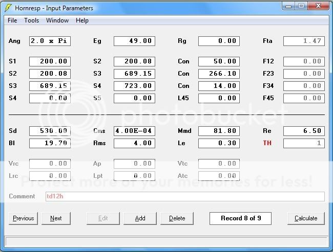
TD12H:
Fs: 26.7 Hz
Qms: 3.72
Qes: 0.25
Qts: 0.23
Vas: 160 Liters
Cms: 0.4 mm/N
Mms: 88.6 grams
Sd: 530 cm2
Rms: 4.0 Kg/S
Bl: 19.7 T/m
Re: 6.5 ohms
Z 8ohms
Le 0.3 mH
Pe (max) 500 Watts
Pe (transient) 1000 Watts
1WSpl: 92.9 dB
Linear Xmax: 14 mm (peak)
Mech Xsus: 18 mm (peak)
Can I get some feedback on these ideas please?
I'm looking for a narrow footprint/ double folded style sub to cover between 35 or 40hz to 100hz. My target is 120db 2pi with 300watts. As I'll be buying some AE drivers anyway, I've looked at them for the subs.
TD12H:
Fs: 26.7 Hz
Qms: 3.72
Qes: 0.25
Qts: 0.23
Vas: 160 Liters
Cms: 0.4 mm/N
Mms: 88.6 grams
Sd: 530 cm2
Rms: 4.0 Kg/S
Bl: 19.7 T/m
Re: 6.5 ohms
Z 8ohms
Le 0.3 mH
Pe (max) 500 Watts
Pe (transient) 1000 Watts
1WSpl: 92.9 dB
Linear Xmax: 14 mm (peak)
Mech Xsus: 18 mm (peak)
Or ideally a smaller driver and box:
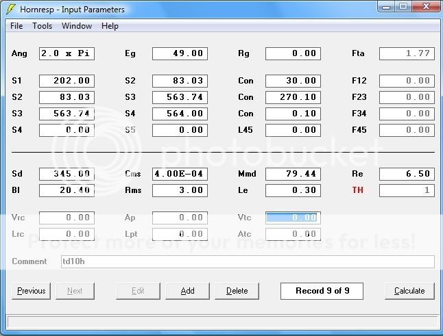
TD10H:
Fs; 27.6 Hz
Qms: 4.88
Qes: 0.23
Qts: 0.22
Vas: 68 Liters
Cms: 0.4 mm/N
Mms: 83 grams
Sd: 345 cm2
Rms: 3.0 Kg/S
Bl: 20.4 T/m
Re: 6.5 ohms
Z 8ohms
Le 0.3 mH
Pe (max) 500 Watts
Pe (transient) 1000 Watts
1WSpl: 90.1 dB
Linear Xmax: 14 mm (peak)
Mech Xsus: 18 mm (peak)
TD10H:
Fs; 27.6 Hz
Qms: 4.88
Qes: 0.23
Qts: 0.22
Vas: 68 Liters
Cms: 0.4 mm/N
Mms: 83 grams
Sd: 345 cm2
Rms: 3.0 Kg/S
Bl: 20.4 T/m
Re: 6.5 ohms
Z 8ohms
Le 0.3 mH
Pe (max) 500 Watts
Pe (transient) 1000 Watts
1WSpl: 90.1 dB
Linear Xmax: 14 mm (peak)
Mech Xsus: 18 mm (peak)
As promised #3
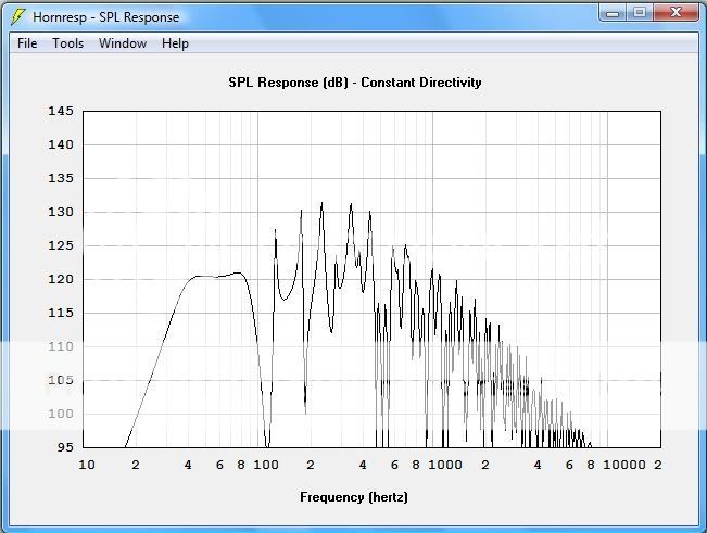
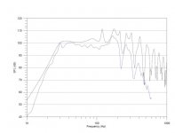
SPL plots for the quad tang band sub.
Modeled in black, measured in blue
Measured with RoomEQ Wizard and the hardware I have described elsewhere using 4 1M datapoint sweeps from 10 to 600 Hz, no smoothing applied. Measurements were close-mic, inside my shop. Sorry I did not do groundplane outdoors. It snowed today - I'm not that hardcore.
Please keep in mind - MY SPL METER IS NOT CALIBRATED.
Attachments
So - now that you see what I've modeled and measured, let the armchair quarterbacking begin.
All in all, I am pleased. My results nearly matched what I modeled.
I did damp the throats with 3/4-inch poly-fill batting stapled to all four sides. This appears to have worked well damping the peak predicted at 120 Hz, but did not help much with the 160 Hz peak. I'll be crossing over at 100 Hz to 120 Hz in this case, so the upper peaks should not matter.
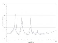
Impedance is interesting - my peaks coincide, but are a little lower in frequency and are definitely lower in magnitude. I may have made the enclosure a little longer than what I modeled, hence the frequency shift. As far as magnitude - maybe the damping material? I do not know.
While playing around with it, I did hear something complaining, though I am still not sure if I was clipping the amplifier, source, or overdriving the speakers. It gets plenty loud - I was measuring 120 dB (with my uncalibrated meter) with it wall loaded (against a flimsy wall). It was loud - windows were flexing visibly.
Thank you to all who have blazed the trail ahead of me.
Thoughts? Comments?
All in all, I am pleased. My results nearly matched what I modeled.
I did damp the throats with 3/4-inch poly-fill batting stapled to all four sides. This appears to have worked well damping the peak predicted at 120 Hz, but did not help much with the 160 Hz peak. I'll be crossing over at 100 Hz to 120 Hz in this case, so the upper peaks should not matter.
Impedance is interesting - my peaks coincide, but are a little lower in frequency and are definitely lower in magnitude. I may have made the enclosure a little longer than what I modeled, hence the frequency shift. As far as magnitude - maybe the damping material? I do not know.
While playing around with it, I did hear something complaining, though I am still not sure if I was clipping the amplifier, source, or overdriving the speakers. It gets plenty loud - I was measuring 120 dB (with my uncalibrated meter) with it wall loaded (against a flimsy wall). It was loud - windows were flexing visibly.
Thank you to all who have blazed the trail ahead of me.
Thoughts? Comments?
Thanks very much for all that littlemike. I'm happy that my added mass t/s measurements are so close to yours, it gives me a bit of confidence in my own project.
Your modelled frequency response curve looks very very similar to a (very) scaled down TH-SPUD so I'd say you are on the right track.
Mine is going to be similar in a lot of ways but quite a bit bigger, tuned a bit lower and a bit less power hungry.
The weather is finally starting to turn and it's warm enough to get working on mine but at the rate I'm going it could be another couple weeks. Mail me if you want to preview my hornresp inputs.
littlemike said:So - now that you see what I've modeled and measured, let the armchair quarterbacking begin.
All in all, I am pleased. My results nearly matched what I modeled.
I did damp the throats with 3/4-inch poly-fill batting stapled to all four sides. This appears to have worked well damping the peak predicted at 120 Hz, but did not help much with the 160 Hz peak. I'll be crossing over at 100 Hz to 120 Hz in this case, so the upper peaks should not matter.
Impedance is interesting - my peaks coincide, but are a little lower in frequency and are definitely lower in magnitude. I may have made the enclosure a little longer than what I modeled, hence the frequency shift. As far as magnitude - maybe the damping material? I do not know.
While playing around with it, I did hear something complaining, though I am still not sure if I was clipping the amplifier, source, or overdriving the speakers. It gets plenty loud - I was measuring 120 dB (with my uncalibrated meter) with it wall loaded (against a flimsy wall). It was loud - windows were flexing visibly.
Thank you to all who have blazed the trail ahead of me.
Thoughts? Comments?
The poly batting you added to the throat will increase the air flow resistance. This would in turn increase the apparent air mass in the throat. This is probably what shifted your impedance peaks down in frequency. All in all, I'd say your modeled vs. measured results are very acceptable. Good job!
Rgs, JLH
littlemike_quad W6-1139
Hi littlemike,
Very well done. A few more pictures of the inside would be helpful, particularly of the batting, the throat chamber and the mouth. I don't quite get what portion of the horn you designate as Vtc-Atc and Ap-Lpt.
Thanks again, Regards,
Hi littlemike,
Very well done. A few more pictures of the inside would be helpful, particularly of the batting, the throat chamber and the mouth. I don't quite get what portion of the horn you designate as Vtc-Atc and Ap-Lpt.
Thanks again, Regards,
Re: TD*H
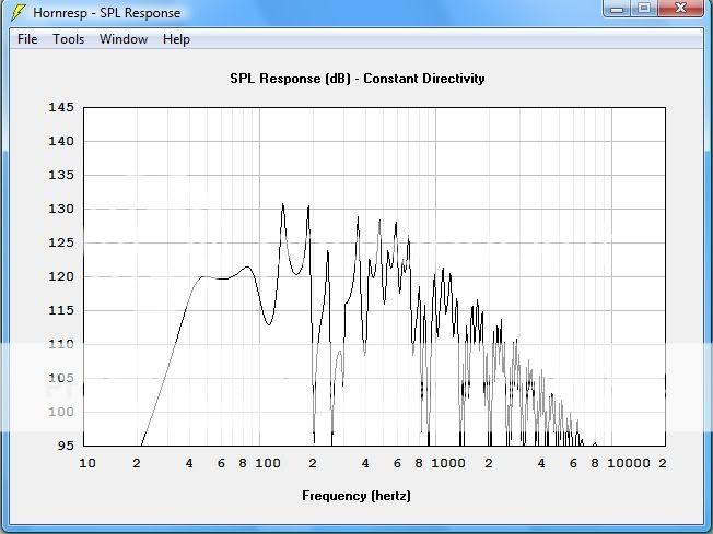
I doubt the deep notch directly above the passband (around 100hz in your sims) will be good for the sound. It will lead to difficulties in crossing over to the midbass box. Try to avoid such notches. You can do this by reducing the length of the first horn segment. Try a value of half the driver diameter as a starting point. This way, you can simply put the driver at the end of the horn, without having to build a front chamber.
fb said:Can I get some feedback on these ideas please?
I doubt the deep notch directly above the passband (around 100hz in your sims) will be good for the sound. It will lead to difficulties in crossing over to the midbass box. Try to avoid such notches. You can do this by reducing the length of the first horn segment. Try a value of half the driver diameter as a starting point. This way, you can simply put the driver at the end of the horn, without having to build a front chamber.
@ tb46
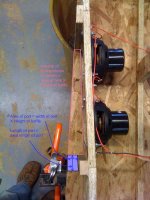
Here is an annotated top view of one of the compression chambers and the port. The "port" is the rectangular piece of wood that partially obstructs the exit of the compression chamber.
I am not 100% sure that I am using the correct terms, but here you go. Hope that this clarifies things.
Here is an annotated top view of one of the compression chambers and the port. The "port" is the rectangular piece of wood that partially obstructs the exit of the compression chamber.
I am not 100% sure that I am using the correct terms, but here you go. Hope that this clarifies things.
Attachments
- Home
- Loudspeakers
- Subwoofers
- Collaborative Tapped horn project