JLH said:
If everyone can be patient and wait for Spring, I will do the proper measurements then.
Understood and thanks for the continuing effort. Looking forward to seeing how ground plane measurements compare to 2pi sims.
GM
Hmm, lest I get nit-picked...
I don't think you need to worry about that. After all these years I'm still struggling to keep up...
Anyway, in my free time when I'm not harrassing JLH I'm doing some modelling with HR to try to figure out what I'm doing without having to make random changes and see what happens. My inspiration is the dts-20. I tried to copy that thing years ago with no software and it was bad. It's still my tapped horn reference, so I'm still hoping to understand it better.
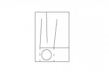
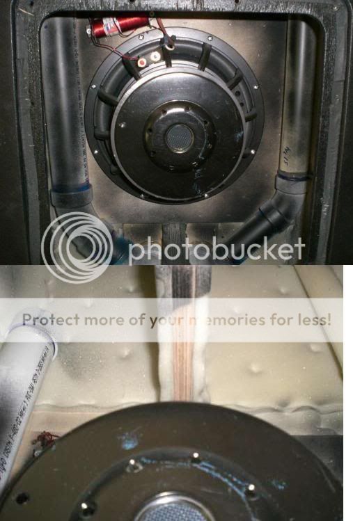
DTS-20 characteristics (IIRC, I lost the internal pics and can't find them) -
- very high throat:mouth ratio, probably more than 1:10
- very long path length, maybe 5.5m or so
- driver taps into the line at the very beginning, and the other (backside) tap is buried quite a way from the mouth - those tap locations seem to be common and key to all the danley designs I've seen inside
- gently rising response, due to tuning the horn about 1 octave below driver fs
So I tried to design something based on my driver that incorporates all those characteristics and hopefully not need extra inductance. The following design is not optomized, this one is a bit trickier to optomize than all of the previous examples I posted.
very low tuned tapped horn, 110L, 43w
An externally hosted image should be here but it was not working when we last tested it.
An externally hosted image should be here but it was not working when we last tested it.
I was able to get the slightly rising smooth(ish) response without extra inductance but at 110L size is becoming a really big issue here. Also remember all my models are done in 1/8 space (corner loaded) so to get decent max spl about 8 of these would be needed. At only 43w to reach xmax, thermal compression is definitely no longer an issue.
I probably won't actually build anything this large, but it's a good excercise. It could be optomized further, and if an extra coil is used it could probably be made smaller. I could probably squeeze 1 or 2 db more out of it too if I play with it. Besides the size issue, this really needs to be run through akabak (where I'm clueless) to determine the optimal size and location of the internal spike killing resonators. If optomized with resonators however, this design would be good from 14 hz almost all the way up to 100 hz.
BUT
I really don't need ~14hz tuning and I also don't really want 8 110L subs in my small/medium size room.
These models of mine just keep getting bigger and bigger, and Volvotreter's tapped horn (without an extra inductor) is starting to look better and better all the time. It's not exactly smooth response, but the size vs spl ratio beats everything I've come up with by no small margin.
I'm still hoping for some in depth criticism on any or all models I've posted. The previous couple of comments are appreciated, but I'm hoping to have any or all of these designs critiqued as brutally and honestly as I did with JLH's model. Most of you have way more experience than me with modelling tapped horns.
I'll be the first to admit that it doesn't look like the previous large tapped horn model has much max spl output, but just to put it in perspective it's good to compare with a ported box, same driver, same (similar at least) tuning.
This does put things in perspective, this looks bleak at best. With a tuning this low, the ports are getting larger than the actual box part. Shown with 130w to reach xmax.
The big tapped horn in the previous post doesn't look quite as bad as it did without a ported reference, but it's still 4x larger.
This does put things in perspective, this looks bleak at best. With a tuning this low, the ports are getting larger than the actual box part. Shown with 130w to reach xmax.
An externally hosted image should be here but it was not working when we last tested it.
The big tapped horn in the previous post doesn't look quite as bad as it did without a ported reference, but it's still 4x larger.
just a guy said:Just because your driveway "taps" into the street does not mean your driveway is adding length to the street. If you measure your street from one end to the other your driveway does not enter into the calculation of the loverall ength of the street in any way.
GM said:
Good analogy
GM
Oh no! GM has decided to join our harassment party.

I promise this is the last thing I’m going to say until proper measurements are made.

It is true that the driveway does not add length to the street, but it sure does add length to your destination. The fact remains that there is a real physical distance that must be traveled in the duct formed by the chamber feeding the horn. It doesn't make any sense to say that the duct distance doesn't physically exist. I have it right in my storage barn if you still have doubts.
I won’t speak of this again until Spring.

Rgs, JLH
Just compare the peaks and dips in the impedance vs hornresp.
http://www.wipo.int/pctdb/en/ia.jsp?ia=US2007/006483
http://www.wipo.int/pctdb/en/wadLis...9/2007&TYPE=A2&DOC_TYPE=PAMPH&PAGE=0&ACCESS=D
http://www.wipo.int/pctdb/en/ia.jsp?ia=US2007/006483
http://www.wipo.int/pctdb/en/wadLis...9/2007&TYPE=A2&DOC_TYPE=PAMPH&PAGE=0&ACCESS=D
JLH said:
The fact remains that there is a real physical distance that must be traveled in the duct formed by the chamber feeding the horn.
Not really AFAIK, the small ducts the drivers fire into are just pressure chambers of uniform particle density in the TH's pass-band, i.e. very high tuned Helmholtz resonators (AKA acoustic low pass filters). Acoustically, they're small enough that I wonder if they are transparent to the driver, making the duct exits effectively very close coupled passive radiators.
GM
JLH said:David,
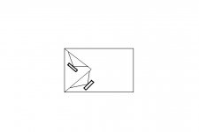
Thank you for your reply. Now here is my question: While Hornresp performs calculations based on L23 and L34 not overlapping, doesn’t my construction method result in having them overlap? In other words, my Hornresp input data is correct for the construction method I used.
Hi JLH,
Without wishing to join the "Harassment Party"
, I would probably use an interpretation similar to yours, but for the purposes of deciding upon the L23 and L34 lengths I would most likely assume that the green and red lines tapered together and converged at the centre-point of the driver, rather than considering the paths to be in parallel at any point.Note that there is no exact answer to this one - it really just highlights the difficulty in applying a relatively simple, idealised simulation model to a real-world physical design. The performance of the original William Cowan type tapped horn layout is probably the one that can be most accurately predicted, since the physical configuration matches the simulation model assumptions reasonably well. I understand that measurements done by William tend to support this assessment.
Using the Hornresp Tapped Horn Wizard for only a few minutes will demonstrate just how critical the precise lengths of L12, L23 and L34 are to the theoretical performance of a three-segment tapped horn. For this reason, any simulation will be somewhat of an approximation at best, no matter how the path lengths are decided upon.
Hope this helps to put things into perspective
.Kind regards,
David
Ok guys, at this point I've posted several design ideas for the tang band w6-1139 in the last couple of pages and asked several times for some concrete feedback. I'd really like to have an in depth technical conversation about possible tapped horns for this driver.
There's several things to consider when trying to pick a design obviously. Max spl vs frequency response vs bandwidth vs power required to reach xmax, and all those type of things. Pros and cons of using an extra coil. How important is it to have the driver feed the line right at the beginning? (As in all Danley designs I've seen and clearly depicted in the patent) Taper ratio vs cone destruction (if you increase the ratio but spl remains the same, is there any added risk?) And there's questions I haven't brought up yet, for example, where exactly do you place the spike absorbing resonators within the line? (See rubens tube explained in the following links - http://en.wikipedia.org/wiki/Rubens'_Tube or this http://www.physics.isu.edu/physdemos/waves/flamtube.htm or this www.youtube.com/watch?v=HpovwbPGEoo or this www.youtube.com/watch?v=VEiEBEadZFI for a very visual explanation of why the resonators have to be placed in exactly the right spot - and note that as with everything else, I could be very wrong about this notion)
On my own I can't answer some of these questions, and in particular, the placement of the resonators is going to require akabak, unless hornresp suddenly is able to calculate a resonator type offshoot from the main line, which I'm not expecting anytime soon or ever.
In other words, without help I'm stuck with limited bandwidth no matter what design I choose, so Volvotreter's horn is the best bet, until I learn akabak, which I never really wanted to do, and which will probably take a long time and make me very grumpy.
So this is the last time I'll ask, as I don't want to seem any more annoying than I already am. Does anyone want to discuss any of my designs or any of the questions I've asked above? Either here or privately, I don't care, pm me if you want. I can build and measure the results, so this conversation would not be a total waste of time on anyone's part. I'll probably end up building more than one design as well, so there could be some good info gained from this.
FROM THE DITCHES On a Hot Day.
I wish I had the knowledge, theory and matchematical skills some of you guys have...but like many of us I don't. Some of you probably think I'm an idiot but, after getting my hands very dirty building over 30 boxes I think I can offer a few puzzles and tips.
I expect some comments and clarifications will be forthcoming from some of you.
Please keep in mind that I have a knack for bridging the gap between laymen (ditch diggers), and engineers as I do both on a daily basis so I may not put things in proper "verbage".
1) Bends make a mess. I have yet to find any formulas or compensation tips on dealing with bends in the computer models.
Bends can add compression, decompression, resonances and unwanted reflections causing phase problems.
2) Ramps. It appears to be true that ramps do not make a damn bit of difference.........below 80hz. However if you are trying to get more upper range out of a tapped horn you are going to need a few. Yes I've tried it. The most critical seems to be toward the throat. I believe a small part of this is simply because the paper cone is more reactive to the effects of pressure in the chamber and reflections from the wood. Also the proximity and angle of sound bouncing back toward the driver from the throat end and the opposite wall cause phase problems before the sound even makes it into the horn. Keeping a smooth flow from driver through the first stage of the horn seems to make for a better sounding box.
3) 4 way tapers, I.E. no parallel walls. If you are trying to really eeek every last db and range out of a box, tapering all 4 sides
does make a big difference, especially in the upper range.
It does make the cabinet bigger unfortunately and bends a royal pain.
4) Wood choices puzzle?
2 identically constructed cabinets, same drivers. One made of mostly birch (or another hard wood if you like), the other out of CDX and sanded ply. Both sealed fairly well and checked 4-5 times during testing to verify construction and measurement accuracy. Both boxes performed fairly equally below 70hz.
Above 70 hz the birch box came alive 4db at 100hz vs the cdx at 98db. The difference in wood choices in a standard W type bin are not as critical to response as those I found in a tapped horn.
It is my opinion that a tapped horn is more akin to a musical instrument like a violin than a standard box or bass horn.
Testing a prototype with CDX is probably O.K due to cost but expect performance to improve in the upper range with good wood.
5) prototype hacking and slashing
Building a screwed and glued prototype is a wonderfull thing unless it does not work. Then it becomes firewood.
If you are prototyping and are expect you may have to really mess with the box's internals, try this.
Assemble the shell minus one side and internals using screws.
Seal the attached side and all joints with either Nashua 324 aluminum duct tape or Nashua Flexfix foil tape. These are air conditioning tapes with adhesives designed to handle pressure.
The flexfix will adhere to flexible ducting like your dryer uses and
is cheaper. I prefer the 324 inside the first stages of the horn due to the pressure as its thicker but both work fine.
You can use the flex fix over older screw holes as you go along and to seal the outside of the box when you put the missing side on. (The next tip avoids that).
Once you have built all but the one side, how on earth do you assemble the last side, sealed so you can remove it? Armaflex air conditioning tape. It's a roll of dense black foam tape about 1/8 of an inch thick with a strong adhesive on one side. Simply use it
on the edges of the internals where they meet the side, trimming it to your woods thickness. When you place the missing side in place and screw it down, it compressed to form a darn good airtight seal. Now you can take it back apart to tweak it, yank off the foil tape to move stuff around, reseal any holes, and go test it again. You'll get a lot of mileage out of that prototype wood and then break it all down for scrap later.
5B. OOOPS I forgot to mark the box to put the screws in.
If you building a couple or more.. Pick up a sheet of 1/2 inch polyfoam insulation. It's foiled on one side and plastic on the other. Layout your cabinet on the sheet using the face and top as a reference edge. You simply cut away areas of the foam core insulation with an exacto knife to make a cheap durable template for marking up your boxes. I usually cut it such that I have an outline of the internals in a multifold box to verify alignments during final construction of the whole mess.
I use a mouth guide as well if I'm tweaking the heck out of a specific design. It fits into the mouth with the face as a reference
edge to align a center assembly for multiple boxes.
6) AIr leaks. Big killer. I've measured up to 6db at 40hz between a tightly built unsealed (unglued) cabinet and a taped one. I've measured a db gain just by sealing one open unused drywall screwhole in the right place in the shell.
7) TOOLS
You can get by with lots of inexpensive stuff but there are a few tools that will make your life very unsatisfying if chosen incorrectly.
JIGSAW... My biggest pet pieve. Go buy a GOOD one. a 50 dollar
Ryobi, Black and Decker, Dewalt or Craftsman is a piece of frustrating garbage. A good one will set you back 150-200 bucks but..... you can haggle at your local pawn shop and get a used one for close to the price of a new cheapie. Cutting baffle holes
is a slow nightmare with a cheap one as well as quick and dirty cuts. A good Jigsaw with good blades is a very handy little buddy when you cant get the circular saw in a space or you are cutting something too small to cut on the circular saw safely.
A good jigsaw is usually a heavy beast but the first time you use it after struggling with a cheapy you will enjoy it so much you might want to build your daughter or granddaughter a doll house
When cutting baffle holes drill a hole bigger than the bit and a bit inside the area to be removed as a start for the saw. Work your way out to your line at an angle like an off ramp on the expressway. I usually drill 4 holes around the area as rest stops.
BITS AND BLADES.
The Titanium coated drillbits (usually gold) last a long time and
cut very well. Once again buy good ones not husky or harbour freight.
I really like the Bosch T shank jigsaw blades. The progressive
clean for wood blades rock, especially with a Bosch saw.
The blu-mol and discount ones are simply a waste or money.
T-SQUARE. Lots of choices here BUT: Be warned that drywall T-squares are not square. The should be but since drywall is not meant to be tightly seamed the QC on the squares is not very high. They are very handy but be sure to check for squareness
at the store using a high quality, fairly long fixed flat machinists square. I use two drywall tee squares and a couple of 3 foot pieces of aluminum. One T is original at 4 feet, the other cut down to 30 inches. I use a 1.5 inch wide aluminum stock as a straight edge and clampable saw guide, and a 3/4 inch as a layout tool for various items.
SAW SLIDES.
I'll Credit BillFitz for this one. Made from wood, your saw rests on the slide which is clamped to the piece you are cutting and allows you to make straight cuts with a hand circular saw.
Excellent tool. I'm sure someboty can post instructions on how to make them.
I also have guides made for different angles without the slide part as setups for angle cuts. These are placed on the line and a piece of steel or aluminum is then clamped behind it as a guide for the saw. Eliminates a lot of remeasuring and mistakes.
Ryobi Drill/countersink/screw bit accessory.
Sweet toy If you only have one drill. It is an atachment and set of bits for your drill. It provides the standard 1/4 inch bit holder
on a reversable shaft, the other end is a combination drill and countersink. You drill and countersink a screw hole, flip the insert around in a second and zing the screw in. All parts are available
in case you break it.
There are a few more but I've gone on long enough.
Edit: Hmm since when is B.U.G.G.E.R a bad word?
Edit: Hmm since when is B.U.G.G.E.R a bad word?
Look it up in the dictionary if you aren't sure exactly what it means. Once you know you probably will never use that word to describe a naughty child again (which is probably the most common usage of the word, albeit wildly inappropriate). Technically it's not really a curse word though.
just a guy said:
I don't think you need to worry about that. After all these years I'm still struggling to keep up...
Anyway, in my free time when I'm not harrassing JLH I'm doing some modelling with HR to try to figure out what I'm doing without having to make random changes and see what happens. My inspiration is the dts-20. I tried to copy that thing years ago with no software and it was bad. It's still my tapped horn reference, so I'm still hoping to understand it better.
DTS-20 characteristics (IIRC, I lost the internal pics and can't find them) -
- very high throat:mouth ratio, probably more than 1:10
- very long path length, maybe 5.5m or so
- driver taps into the line at the very beginning, and the other (backside) tap is buried quite a way from the mouth - those tap locations seem to be common and key to all the danley designs I've seen inside
- gently rising response, due to tuning the horn about 1 octave below driver fs
So I tried to design something based on my driver that incorporates all those characteristics and hopefully not need extra inductance. The following design is not optomized, this one is a bit trickier to optomize than all of the previous examples I posted.
very low tuned tapped horn, 110L, 43w
An externally hosted image should be here but it was not working when we last tested it.
An externally hosted image should be here but it was not working when we last tested it.
I was able to get the slightly rising smooth(ish) response without extra inductance but at 110L size is becoming a really big issue here. Also remember all my models are done in 1/8 space (corner loaded) so to get decent max spl about 8 of these would be needed. At only 43w to reach xmax, thermal compression is definitely no longer an issue.
I probably won't actually build anything this large, but it's a good excercise. It could be optomized further, and if an extra coil is used it could probably be made smaller. I could probably squeeze 1 or 2 db more out of it too if I play with it. Besides the size issue, this really needs to be run through akabak (where I'm clueless) to determine the optimal size and location of the internal spike killing resonators. If optomized with resonators however, this design would be good from 14 hz almost all the way up to 100 hz.
BUT
I really don't need ~14hz tuning and I also don't really want 8 110L subs in my small/medium size room.
These models of mine just keep getting bigger and bigger, and Volvotreter's tapped horn (without an extra inductor) is starting to look better and better all the time. It's not exactly smooth response, but the size vs spl ratio beats everything I've come up with by no small margin.
I'm still hoping for some in depth criticism on any or all models I've posted. The previous couple of comments are appreciated, but I'm hoping to have any or all of these designs critiqued as brutally and honestly as I did with JLH's model. Most of you have way more experience than me with modelling tapped horns.
Some where on this thread I posted some stuff on my attempt at getting close to the DTS-20. And I did Ok all things considered.
Somehow I doubt that the DTS 20 has a compression ratio anywhere close to 10:1.
I shot for 3:1
I'll second the request for info about resonators. Both of mine will be behind walls so it will be easy to drill a hole and put one in and experiment with length.
Here's my take on the resonators.
1. They are absolutely required to get more bandwidth than the average diy tapped horn. This part is obvious enough. The commercial models are getting at least an octave more than any diy design I've seen.
2. Without the extra bandwidth that the resonators provide, a 6th order bandpass can do approximately the same spl (or more) and similar bandwidth (maybe a bit less) in the same size package. The only advantage the average diy tapped horn has over 6th order bandpass is no port compression.
3. I suspect the resonator opening must be placed very carefully to get full effect. If my theory about the placement can indeed be visualized by the rubens tube effect, there may actually be several optimal places to locate the opening, but precise placement on one of the standing waves of the problem frequency is still paramount.
4. The dts-20 uses lengths of pipe for resonators. I have no idea how long they are. Pipes obviously have pipe resonances, so if a single long skinny resonator is used it may possibly be persuaded to kill both of the tapped horns twin peaks. That would be a handy little trick indeed. But it would not be a trivial task to design, for me at least. There are helmholtz calculators online but IIRC they only calculate frequency vs volume and do not take shape into account. So the volume AND shape of the resonators may be critcal as well as the placement issue.
Maybe I'm overthinking this, but IMO it's best to be prepared for what could happen during prototype testing. Personally I'm going to hold off on learning akabak as long as possible, opting for real physical tests and measurements instead. I'm going to take pipes of different cross sectional areas and lengths (with one end covered) and shove them up the backside of my bib and do a series of measurements at different positions in the line, probably inch by inch until I have a sweet spot and then cm by cm. Each different pipe I test will have the approximate helmholtz resonance frequency as the first tapped horn peak as an initial starting point.
That should give you a bit to chew on, but since my methodology is not scientific and I won't be able to actually confirm anything without learning akabak, and because there is almost zero interest in this area I'm not going to press this issue any further.
Somehow I doubt that the DTS 20 has a compression ratio anywhere close to 10:1.
Can you post the hornresp inputs you used (assuming you used hornresp)? I only saw one pic a LONG time ago, and IIRC the driver tapped into the beginning of the line with a hole smaller than the cone area, and mouth area was maybe 3x cone area.
Apparently IDRC. (I don't remember correctly.)
EDIT - please disregard that request, it just occurred to me that I can look it up my own lazy self.
- Home
- Loudspeakers
- Subwoofers
- Collaborative Tapped horn project