You know I have read that but I guess it didn't really stick. The reason is he goes into detail about how adding caps after the rail splitter can have adverse affects. Then generally says not to do it. Thats right after he said that he had to do it in the MINT.
I thought that was the point anyway?
He cautions about it possibly causing the TLE to become unstable.
He doesn't really say what kind if capacitive load the TLE2426 can handle. However, in the MINT amp he has 330uf caps after the splitter. I had planned on using 100uf caps. Should those be sufficient to keep the TLE2426 in the safe zone in this circuit?
I had planned to use OPA2132 and OPA2227. The latter possibly consuming more current.
An active virtual ground circuit has some "bandwidth": that is, it will be effective over some range of frequencies. If you put capacitors across its output, that lowers its bandwidth: as frequency goes up, the capacitors are "in charge" to a greater and greater extent. If the caps are large enough, the virtual ground circuit's bandwidth is completely swamped. It could end up being good for no more than maintaining the DC level of virtual ground.
I thought that was the point anyway?
He cautions about it possibly causing the TLE to become unstable.
Another potential problem with big caps on the output of a virtual ground splitter has to do with stability. Some circuits will become very stable in this situation: no bandwidth and no gain, hence no oscillation. Most circuits aren't made to cope with capacitive loads, however. They become less stable when driving a capacitive load. Study the datasheets for the ICs you will be using. Unless they specifically tout the fact that they can drive large capacitive loads, beware of using them in virtual ground circuits.
He doesn't really say what kind if capacitive load the TLE2426 can handle. However, in the MINT amp he has 330uf caps after the splitter. I had planned on using 100uf caps. Should those be sufficient to keep the TLE2426 in the safe zone in this circuit?
I had planned to use OPA2132 and OPA2227. The latter possibly consuming more current.
Those comments don't apply specifically to the TLE2426 - generally, it's fine about driving a capacitive load. He's saying that it can be an issue when "rolling your own" with a buffered resistive divider using certain opamps.
Actually, I'm sure the TLE doesn't mind the capacitive load, the PIMETA is set up with the caps after the splitter, and I've got one here with 4 x 470uF, 2 in parallel on each rail.
100uF is probably sufficient to handle transient current demand, but if you can fit 330 in the required footprint, I'd go for it.
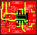
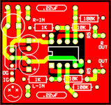
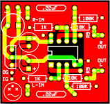
I made a few changes to the ground trace. I'm not really sure if this is better than it was before. It seems to me like it would be, but I'm no expert. Now the IG, OG, TLE, and rail caps have a dedicated trace. The caps are connected to the ground plane via thermal.
I haven't bothered trying to jump the gun on ordering these things. It's not like if I ordered tomorrow I would get them any time soon due to the holidays. Batch PCB isn't exactly the fastest as it is.")
If you guys see any potential problem let the critique fly and I'll get back to work.
I haven't bothered trying to jump the gun on ordering these things. It's not like if I ordered tomorrow I would get them any time soon due to the holidays. Batch PCB isn't exactly the fastest as it is.
If you guys see any potential problem let the critique fly and I'll get back to work.
Attachments
Hi,
With the connection you currently have the input groung and the output ground share a track back to your star point (the pin on the ground splitter).
You want the output ground to have its own track to the pin on the ground splitter and the input gound plane to have a seperate track to the pin on the ground splitter. So no copper is shared by the ground return currents from the output and the input signal grounds.
Regards,
Andrew
It went fine magnum. I had four of these made and built them all.
What I learned.
1. The rail splitter is a bad idea. Real ground is best.
2. Air wired in/out and pot is absolutely the way to go. After trying to case up some JDS boards recently, I knew I had made the right decision with my design. You DON'T want board mounted connectors for an amp designed to be cased in a mint tin. Save that for your CNC routed front panels for real amps.
3. I guess everyone builds a C-moy as a first project. It was actually my second. I built a headbanger as a first project and I feel that is is actually the better amp in many ways. Its clarity and presentation can't compete with the C-moy, but it's usability far outweighs that.
There is basically no opamp on the planet that can do what a C-moy asks of it. The C-moy is a preamp. You can make it drive phones if you want. It will never be right for that. It is an excellent gain stage. It will require a buffer to drive anything substantial. You see people telling me exactly that throughout this thread and in others of the same subject matter.
My head is hard. I'm telling anyone willing to listen. Don't build a C-moy as your first project. Build some version of an A47 and you'll be way better off. It's just as easy as a C-moy and miles ahead.
Rail splitter ICs like TLE2426 are best used just to create a reference, midpoint voltage, like in a Pimeta where your ground return is a separate channel, or A47 where there's still a buffered ground.
Opinions will vary but I see no reason to build an A47 unless someone has extra opamps lying around. I mean, it is a significant step better than a CMOY, but skip the 2nd opamp in A47 and put a push pull discrete buffer within the feedback loop. It's not many more parts, about same, sometimes less expensive than a 2nd *good* opamp, and IMO, sounds better as well as greatly increasing current capability (depending on transistors chosen), giving bass an effortless appearance and treble more definition.
Opinions will vary but I see no reason to build an A47 unless someone has extra opamps lying around. I mean, it is a significant step better than a CMOY, but skip the 2nd opamp in A47 and put a push pull discrete buffer within the feedback loop. It's not many more parts, about same, sometimes less expensive than a 2nd *good* opamp, and IMO, sounds better as well as greatly increasing current capability (depending on transistors chosen), giving bass an effortless appearance and treble more definition.
Last edited:
^^^ Yea I don't really subscribe to that. I know for a fact that no discrete buffer is going to be better over all than an op-amp buffer. Nor is it cheaper or easier to implement.
That is a placebo. Something a lot of discrete builders would like to tell you is true but it isn't. If discrete were better, then op amps would have never been invented. OP amps are an improvement over discrete designs in form factor and almost every other way as well.
Sure you can cherry pick your battles or claim to be more powerful than any one opamp. However, one finds op amps that are made for audio applications, are miles ahead of the same discrete circuit.
The A47 is an ok design. Though I don't agree with the use of 47-Ohm output resistors or a ground channel. You could get away with much lower matching resistors and real ground is always the best ground.
^ You might be failing to consider that the opamp is in control when the discrete buffer is in the feedback loop, that the discrete buffer has great benefit because it is capable of higher current to drive a load while the (typical ones people use) opamp is so poor at that even using two in parallel. Have you ever built one?
I have done it both ways. The opamp with discrete (or BUF634 and other ICs) buffer headamp sounds much better than the others. Typical opamps need a buffer unless driving a very high z load. You claim opamps are better or else they wouldn't have been invented, but the same is true of a buffer in general, that if opamps were better there wouldn't have been IC buffers OR discrete ones invented, and put into the headamp circuits used.
Also it is often cheaper than a 2nd opamp (unless you use very poor (cheap) opamps that sounded terrible driving cans already), and easy to implement. Some might tell you to use exotic parts but 4 transistors and a few resistors (under $1 worth of parts in a minimized version) can accomplish this, or less than $10 with more discrimination over parts, which is at parity with many opamps people use.
Many things we discuss by adding components make only a small difference but THIS, buffering the opamps is a HUGE improvement.
It is as easy as using same design(s) others use, if you don't want to invent something new - same as with opamps alone.
Last edited:
^^ A ground channel is also a good improvement. I mean a *channel* with low impedance, not just virtual ground versus a split rail power supply, but even without a feedback loop, with just the railsplitter and BUF634, the noise rejection increases enough that you can literally power an A47 with an unregulated linear wall wart and get rid of the majority of 100/120Hz line hum you would hear on a CMOY headamp.
A ground channel is most certainly not better than a true ground. The only thing a ground channel offers in a headphone amp is greater noise, crosstalk and greater output impedance. All things you wish to be lower.
You will never be able to make a ground channel with as low impedance as the real ground. This has been tested before. By people much smarter than I, with expensive equipment.
A ground channel is a easy way to add some type of protection to battery powered amps. A better way is to monitor the rails for failure. There is a reason that the Grado Ra-1 uses a real ground. As dangerous as it may be, If it screws up a set of phones, they can just replace them. After all, they make them.
^ Definitely false and almost completely backwards, the ground return contaminates the signal ground without a ground channel. A ground channel REDUCES crosstalk. This has been tested and proven by many people (driving a load as required for valid data, not loopback tests) so I have no idea what you are suggesting. Please link to one using a ground _channel_ (not just rail-splitter) implemented reasonably that tests worse. Keep in mind, a ground channel does not keep one from using a split rail PSU if one so desires.
Grado RA-1 isn't a particularly good amp, it's merely better than sources that can't drive cans very well but in the grand scheme of things it can't either. I have no idea why you mention it, that amp is sort of a joke for how poor it is considering the price... it even uses the lowly JR4556 opamp but supposed audiophiles who never heard anything better just assume the excessive cost of the headamp must mean it's good. Only thing it really has going for it is the fancy case, and of course the name on it.
I highly recommend you visit headfi.org and look over their better amp projects, or here is one among many that is far far better than what you're suggesting, and I quote (this was tested too!):
The β22 Stereo Amplifier
... or if you want a lot of discussion about it, I suggest the following link and post the question, "Is it of benefit for a headamp to have a ground channel and why?"... except, essentially this has been asked and answered many times before so do a forum search and you will find years of discussion and education on the topic:
DIY (Do-It-Yourself) Discussions
What "protection" are you suggesting a ground channel offers in a battery powered amp? Protection from batteries draining at different rates?
Grado RA-1 isn't a particularly good amp, it's merely better than sources that can't drive cans very well but in the grand scheme of things it can't either. I have no idea why you mention it, that amp is sort of a joke for how poor it is considering the price... it even uses the lowly JR4556 opamp but supposed audiophiles who never heard anything better just assume the excessive cost of the headamp must mean it's good. Only thing it really has going for it is the fancy case, and of course the name on it.
I highly recommend you visit headfi.org and look over their better amp projects, or here is one among many that is far far better than what you're suggesting, and I quote (this was tested too!):
Source:AMB said:3-channel "active ground" amplifier (3 β22 boards required)
This is the recommended configuration for standard 3-wire headphones, and offers improved performance by having an active ground channel amplifier for the headphone's shared "ground return" wire. The ground channel amplifier sources or sinks the return current from the transducers, which would otherwise have been dumped into signal ground or power supply ground. This shifts responsibility for the high current reactive load of the headphones from signal ground to the tightly regulated power supply rails, thus removing the primary source of signal ground contamination. The headphone transducer "sees" symmetrical output buffers with equal impedance and transfer characteristics on both sides, rather than an amplifier on one side and a capacitor bank of the power supply ground on the other. This results in lower output impedance, greater linearity and reduced stereo crosstalk.
The β22 Stereo Amplifier
... or if you want a lot of discussion about it, I suggest the following link and post the question, "Is it of benefit for a headamp to have a ground channel and why?"... except, essentially this has been asked and answered many times before so do a forum search and you will find years of discussion and education on the topic:
DIY (Do-It-Yourself) Discussions
What "protection" are you suggesting a ground channel offers in a battery powered amp? Protection from batteries draining at different rates?
Last edited:
@!
Why not read the info at this link:- NwAvGuy: Virtual Grounds & 3 Channel Amps
While you're at it read this page too:- NwAvGuy: AMB Mini3 DIY Headphone Amp
...and see how your authority AMB has discredited himself by refusing to acknowledge justified criticism of his engineering.
Why not read the info at this link:- NwAvGuy: Virtual Grounds & 3 Channel Amps
While you're at it read this page too:- NwAvGuy: AMB Mini3 DIY Headphone Amp
...and see how your authority AMB has discredited himself by refusing to acknowledge justified criticism of his engineering.
counter culture, your links do not work because of a session ID embedded in them. I don't know why you linked through a proxy but regardless, here they are working w/o a proxy session ID for others' reading.
NwAvGuy: Virtual Grounds & 3 Channel Amps
NwAvGuy: AMB Mini3 DIY Headphone Amp
On the Mini3 he pretends to do valid measurements but look at what he actually did. Testing at 15 ohms... how many 15 ohm headphones do you own? Most people have never seen such a beast. Publishing a rating of "poor" for THD of 0.45% into that 15 ohms but not even mentioning the power level... pretty fishy, anyone can make THD rise by pushing the power level. Crosstalk also at 15 ohms, but not even negative values??? Fishy.
The author makes a false assumption that the ground impedance is only from an inch of wire, does he think the positive and negative rail impedance is also only an inch of wire each too? He must then, so his argument is that your entire power supply impedance comes from the two inches of connecting wire.
False assumptions can predicate further false assumptions.
When criticism isn't justified, you don't drop everything and entertain someone.
For example, if I stated someone is too short to play basketball and the person wasn't short nor did they want to play basketball, would that person feel compelled to stop what they are doing and address the comment? Perhaps for an instant but not for long if at all.
^ yes, designing a headamp for only one set of cans would be very counter productive unless you clearly state that you are deceiving everyone to try to win an argument.
How about reality instead?
Listen to an amp then decide. I know it is a novel concept but it is worth doing.
Bottom line - I have built these amps, there is no contest, it is not even close and to suggest otherwise seems ludicrous after hearing them. Have you??
How about reality instead?
Listen to an amp then decide. I know it is a novel concept but it is worth doing.
Bottom line - I have built these amps, there is no contest, it is not even close and to suggest otherwise seems ludicrous after hearing them. Have you??
- Status
- This old topic is closed. If you want to reopen this topic, contact a moderator using the "Report Post" button.
- Home
- Amplifiers
- Chip Amps
- Cmoy layout.