

HifiNutNut,
You wrote:
Baffle comp is already in my measurements. Because I've measured the frequency response of my drivers when they were inside the cabined already. So I have the real baffle reflections.
When you do this by software then it is only what you expect not what it is in reality. So the best way is always to take measurements.
")
You wrote:
Have you included the baffle response into your XO?
Baffle comp is already in my measurements. Because I've measured the frequency response of my drivers when they were inside the cabined already. So I have the real baffle reflections.
When you do this by software then it is only what you expect not what it is in reality. So the best way is always to take measurements.
Ok but I use the 8545K00. This speaker is less flat in response and goes a little lower in frequency.I have never used anything more than LCL on the 8545.
Jonasa,
If your driver response measurement was taken when it is mounted on the speaker, it will be fine.
Flat response is important. Also important are power response and radiation patterns.
I always find XOs with less components sound better provided that they have the same FR and power response. Less reactive elements in the XO the better. No capactors sound good. They all colour the sound to various extends. Large inductance also generates more back EMF and make it difficult to drive by the amplifier. The way I do it is normally a CL to get an electronic LR4 for the HP, and most of the time a LC to get an electronic LR4 for the LP. I mainly do hybrid passive and active 3 way. So only small inductors are used. Baffle step is compensated in the active circuit, obtaining a low insertion loss. In my WWMTMWW speaker I used only two opamps per frequency range.
ttan98,
It depends. I have medium size room and I always place my speakers at least 1.2m from the walls so full compensation may be necessary.
I use the Edge, BSC from FRC, and A B C Dipole from John K. They are all different and are all useful.
Jonasa,
I would be interesting to know the performance of your x-over.
most people use very simple 2, 3 or most 4 order x-over without phase correction. Sometimes bumps and notches are corrected most designers don't even bother to do so. For eg.,J D'Appolitto's design based on 8945 which is similar to scanspeak 8945 don't even correct bump at 800-900 Hz or phase correct at x-over frequency.
By the way I am also designing a 2 way usher 8945 woofer and maybe usher tweeter. Your design is of interest to me.
cheers...
Hi everyone,
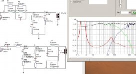
I've finally ordere my components to build my own designed crossover. When the components arrived I'll do a lot of new measurements that I want to share with everybody.
Below you see my final crossover that I'm going to build. I've changed the design a little bit. As you can see I've used a higher order for the tweeter.
My plans are building this crossover on a separated plate outside the speaker and when everything souds fine then the latest step is to fit evererything together insed the box.
Tesson,
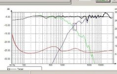
I don't think it is complex. Just you need lot of components to get this flatness ....
You can use only expensive components for a few capacitors in the path of the tweeter. When you look a few posts back you will find an explanation of every part in the crossover.
Now I want to know how it will measure and sound when I've build it in reality.
Jonasa said:Tesson,
I don't think it is complex. Just you need lot of components to get this flatness ....
You can use only expensive components for a few capacitors in the path of the tweeter. When you look a few posts back you will find an explanation of every part in the crossover.
Now I want to know how it will measure and sound when I've build it in reality.
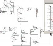
The circuit IS complex in the common use of the word, when related to passive crossovers. I hope it sounds good.
Tenson said:What do C10, C11 and L10 and L11 do? Is that phase shift?
Yes.
- Status
- This old topic is closed. If you want to reopen this topic, contact a moderator using the "Report Post" button.
- Home
- Loudspeakers
- Multi-Way
- Closed box design:Scan Speak monitor