Hi,
Hmmm.... not sure I follow these ideas. Can I clarify a few things ?
First, if the clock is powered by it's own dedicated psu, as is best practice for noisy logic circuits, then no decoupling is necessary ? Decouple from what ? Perhaps you mean hf bypassing with something like x7r ceramics ?
Second, if the clock has its own dedicated psu, then bandwidth/output impedance is not such an issue because clocks are quite high impedance devices themselves - their current drain is ~15mA @ 3.3V. Of course, ocxo's are ~100-300mA but most smd/dip clocks are low current devices. What matters is noise ? Esp low frequency noise ?
If I'm way off base, please explain !
Cheers,
Tom
Klipsch...
I am no expert, but this is my suspicion:
With a very low noise supply, like a good shunt reg, locally right at the oscillator, you would only want the high speed ceramic (as you note) cap right at the input of the clock. Bigger caps would be unnecessary because the output impedance and bandwidth of a good shunt is better than that of say, a bigger electrolytic or polymer cap.
Even with an isolated/dedicated supply, a low output impedance could still be a benefit as the low output impedance can stop the clock signal from modulating the supply-travelling backwards to the AC input, and modulating the other supplies from there. Of course, in the real world, how big a difference will this make??? I do not know, but I am a fan of powering oscillators with a local mini shunt.
Cool... that's right where I'm at too, although I'm more inclined to series regs than shunts mostly because most shunt makers don't publish their noise specs. Twisted Pear, Paul Hynes, Guido Tent... I can find no specs. Am I missing something ?
I think a li-ion battery, filtered, regulated, and then bypassed with 47pf, 470pf, 4.7nF and a low esr polymer cap like a Nichicon PLE is the best option.
Something like this, with more caps, and with the en pin tied to an internal supply so the reg switches off when the DAC does. The mcp73861 is a safe charger for a single li-ion cell and can run from a 7805 for charging.
The adp150 has very low noise and good bandwidth so that's become my preferred choice.
I suspect most transf. don't have the bandwidth to carry the noise through but the main problem with mains is the low frequencies. Most sites I have read seem to suggest this is the major problem.
I think a li-ion battery, filtered, regulated, and then bypassed with 47pf, 470pf, 4.7nF and a low esr polymer cap like a Nichicon PLE is the best option.
Something like this, with more caps, and with the en pin tied to an internal supply so the reg switches off when the DAC does. The mcp73861 is a safe charger for a single li-ion cell and can run from a 7805 for charging.
An externally hosted image should be here but it was not working when we last tested it.
The adp150 has very low noise and good bandwidth so that's become my preferred choice.
I suspect most transf. don't have the bandwidth to carry the noise through but the main problem with mains is the low frequencies. Most sites I have read seem to suggest this is the major problem.
Last edited:
I like shunts....
I have always gotten better subjective results using shunts than LiFePO4s, plus I hate charging hassles!
Paul Hynes does publish noise specs for his regs. which are almost unbelievably good...
TPA does not. Most of these regs are really low noise, and would probably require an AP2 to get relaible measurements-how many people have access to an AP2?
I would love to see reliable measurements of some of these regs, but most measurements shown here at DIYa seem to be dominated by the noise floor of the measuring device, a cheap soundcard and some software is not going to cut it!
To really know what approach would be best, someone would need to test the individual oscillators with differnet supplies/circuits, and measure the oscillator output for phase noise-tough to do without really good test gear...
Anyone out there have real, accurate measurements of regulators and clock circuits?
Hi,
Although some time ago this thread was active I hope one of you can give a quick feedback on this:
I'm currently designing a circuitry using the NZ2520S crystal from NDK, however, looking at their datasheet I cannot see if the pads are seen from above or from the bottom. One of you knows?
Best regards,
Jesper
Attachments
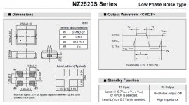
above, its a fully surface mount component
Hey - thanks for replying... Are you sure? The Crystek CCHD-997 (I think it is) sees the chip from the bottom in their datasheet (similar to the lower left corner pad layout on the NDK image attached).
Best regards,
Jesper
Hi both - thank you for your replies - to me it's quite special to be able to get help from others in a forum like this ;-)
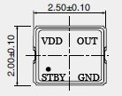
Just to make sure I've inserted a thumbnail of the crystal seen from the top but with the pad configuration shown as if I was looking down from the top - through the crystal. Is it right now?
Greetings,
Jesper
Just to make sure I've inserted a thumbnail of the crystal seen from the top but with the pad configuration shown as if I was looking down from the top - through the crystal. Is it right now?
Greetings,
Jesper
Attachments
")
my apologies, I saw the plan view with the dot and didnt think further. what a stupid diagram… being SMD who will ever be looking at the bottom of the chip when working out which pin is which and landing patterns will only ever be on the side of the board where the part is, so what point is it to know what pin is what from underneath as the only view? ie the pads will never look like that.
is it that they are giving you the landing patterns already for litho?
wow your right, my CCHD-975 DS has the same thing. could be a left over standard from PTH parts?
I would have thought datasheets should portray information in a literal manner in the way it will be used, not catering for some outmoded standard. it makes no sense, sure have a pic of the part like that if you must, but reversed landing patterns to match it? weird.
Last edited:
Cool... that's right where I'm at too, although I'm more inclined to series regs than shunts mostly because most shunt makers don't publish their noise specs. Twisted Pear, Paul Hynes, Guido Tent... I can find no specs. Am I missing something ?
You will find this interesting I think:
http://www.linearaudio.net/images/letters.pdf/V4 JW F7.pdf
Sorry for my reaction to a post from more than a year ago......
Last edited:
Where will you source the ndk xo?
Hi studiostevus,
I intend to source them from chip1stop which Bunpeis links to in a previous post. If you are interested then send me a PM and I can say a bit more about price etc.
Greetings,
Jesper
- Status
- This old topic is closed. If you want to reopen this topic, contact a moderator using the "Report Post" button.
- Home
- Source & Line
- Digital Source
- Clock Selection Experts?