I´ll lok some more into it 🙂
But;
If the top most (NPN for ex.) opens while the lower (PNP) closes, then the - VS does not effectively "draw" current from the NPN anymore meaning that the NPN must open up only to MAINTAIN it´s idle current.
The NPN emitter shifts from delivering current into a GND potential (zero ohms) to delivering current thru the speaker ( "8 ohm"), so I still see it like the max ouput current is = idle current, otherwise the amp enters clas AB.
Would like someone ho knows this for real could chime in.
Efficiency however depends on if the device is loaded with a resistor, a coil or a active constant current source.
My class A amps idle at 300-350W or so but only put out 78W/8 ohm in class A, meaning efficicency of about 25%.
The Pass Aleph series I believe has about 30% efficiency if compared rated output in 8 ohm to idle.
A resistorloaded single end amp has efficicency of 10-20% or so.
If I remember correct the most efficient type of class A amp is a inductor loaded one, like the one Circlotron is working with.
/Peter
I´ll try to explain
Lets assume a very simplistic class A power follower.
We assume that we have a 8 ohm resistive load (best case scenario).
We make a PS of two 8V batteries for a +/-8V PS.
Now we pretend we have this circuit of two batteries, one 8ohm load and two transistors, one NPN and one PNP for a typical class A complementary amp.
Forgett about bias and idle for a second and just look at max power/current which is when one transistor is off and one is open.
Then we get 8V/8ohm=1A.
Max power from this circuit is the equivalent to 1A into 8ohm which is I"2"xR = 1 x 8 = 8W.
This is a 8W class a amp. To be able to deliver this 1A or 8W into 8ohm in class A, we need to bias the NPN and PNP devices to conduct the full power current (to be precise we need just a tiny bit more to always stay in class A), which is 1A.
By biasing the devices in full class A we adjust until 1A flows thru both devices. What goes into the NPN must pass the PNP as well and nothing goes out thru the hot terminal because we have perfect DC stability on the output.
Now, by dynamically adjusting the transistors we can shunt the current via the 8ohm load to GND by creating a potential at the midpoint between the two transistor ie. the "hot out" from the amp. We can never manage to get more than 1A from one side of the PS since 8V/8ohm = 1A.
The load can never receive current equivalent to 16V but only 8V.
We can bias the idle of the transistors for more than 1A, we can make close to a short and bias for 100A if we want, but we will never be able to put more than 1A into the load.
Clear now friends?
/Peter
Once more then. The peak class-A output current of a push-pull stage is twice its idle current. If you pull out more the stage operates in class-AB.
If you don't believe this then please go through the math, or simulate it.
If you don't believe this then please go through the math, or simulate it.
Re: I´ll try to explain
Correct.
In theory, allmost. You're hitting the limit of class A, since the transistors are actually turning off. The nonlinearity that occours when a transistor is approaching turned off mode is not compatible with class A
Meaning????
Asuming the transistors are like switches, wich they're not !
Pan said:I´ll lok some more into it 🙂
But;
If the top most (NPN for ex.) opens while the lower (PNP) closes, then the - VS does not effectively "draw" current from the NPN anymore meaning that the NPN must open up only to MAINTAIN it´s idle current.
Correct.
Pan said:The NPN emitter shifts from delivering current into a GND potential (zero ohms) to delivering current thru the speaker ( "8 ohm"), so I still see it like the max ouput current is = idle current, otherwise the amp enters clas AB.
In theory, allmost. You're hitting the limit of class A, since the transistors are actually turning off. The nonlinearity that occours when a transistor is approaching turned off mode is not compatible with class A
Pan said:Would like someone ho knows this for real could chime in.
/Peter
Meaning????
Pan said:Lets assume a very simplistic class A power follower.
We assume that we have a 8 ohm resistive load (best case scenario).
We make a PS of two 8V batteries for a +/-8V PS.
Now we pretend we have this circuit of two batteries, one 8ohm load and two transistors, one NPN and one PNP for a typical class A complementary amp.
Forgett about bias and idle for a second and just look at max power/current which is when one transistor is off and one is open.
Then we get 8V/8ohm=1A.
Asuming the transistors are like switches, wich they're not !
Pan said:To be able to deliver this 1A or 8W into 8ohm in class A, we need to bias the NPN and PNP devices to conduct the full power current (to be precise we need just a tiny bit more to always stay in class A), which is 1A.Just a bit more!
Pan said:Now, by dynamically adjusting the transistors we can shunt the current via the 8ohm load to GND by creating a potential at the midpoint between the two transistor ie. the "hot out" from the amp. We can never manage to get more than 1A from one side of the PS since 8V/8ohm = 1A.Yes.
Pan said:The load can never receive current equivalent to 16V but only 8V.Correct!
Pan said:We can bias the idle of the transistors for more than 1A, we can make close to a short and bias for 100A if we want, but we will never be able to put more than 1A into the load.Correct!
Pan said:Clear now friends?
/Peter
We're getting close, even to reality !
To be or not...class A...
Correct!!!!
Cheers
The peak class-A output current of a push-pull stage is twice its idle current. If you pull out more the stage operates in class-AB.
Correct!!!!
Cheers
Pan said:
Efficiency however depends on if the device is loaded with a resistor, a coil or a active constant current source.
My class A amps idle at 300-350W or so but only put out 78W/8 ohm in class A, meaning efficicency of about 25%.
The Pass Aleph series I believe has about 30% efficiency if compared rated output in 8 ohm to idle.
A resistorloaded single end amp has efficicency of 10-20% or so.
If I remember correct the most efficient type of class A amp is a inductor loaded one, like the one Circlotron is working with.
/Peter
Hmm.. I must stop eating those mushrooms. I was mixing up somehow, power at idle and rated power with max efficiency, which obviously are two different beasts.
/Peter
Werner said:Once more then. The peak class-A output current of a push-pull stage is twice its idle current. If you pull out more the stage operates in class-AB.
If you don't believe this then please go through the math, or simulate it.
Please read my explanation and tell me what I miss?
Also please explain how the peak class A current can be double the idle?
Maybe we all should clarify if we talk about a complementary SS amp or a diffrential amp (tube or SS). But I think a diff. amp also put out max the total idle current, which is twice the current in each leg. NO wait a minute, a diff. amp only put out 0.5 times the total idle current.
NOOOO wait again 😀 it depends on if the amp is loaded with constant current sources or if it´s a bridged complementary amp.
I think:
a complementary class A SS amp can only out put idle current into the load, then it enters class AB.
A differential "balanced single end" amp, only puts 1/2 the idle current thru the load IF IT`S loaded with CCS.
Whatabout a diff. balanced single end amp with resistor load?
A bridged complementary class A SS amp can put 1x total idle into load (which is the same as 2x idle in each leg).
Must stop thinking for a while, my head hurts as I draw those pictures in my mind and do not use paper and pen 🙂
Good brain gymnastics.
/Peter
"Maybe we all should clarify if we talk about a complementary SS amp or a "
Push-pull I wrote, like 97.3% of all audio
amplifiers out there. Meaning an output stage with two legs, one +, one -, on top of each other (i.e. loading each other), both driven, both behaving in a complementary way, either by virtue of the output devices being so (NPN/PNP), or by means of a phase-splitter as in a tube amp.
Right then. At idle both legs carry idle current I, and the output voltage is zero.
When the signal goes positive, the upper device is asked to carry a current I+deltaI, the lower device is asked to carry current I-deltaI. The difference of these two currents must go to the load. The difference is 2 times deltaI.
The lower device cuts off when deltaI equals idle current I. At that time the upper device carries a current of I+deltaI = I+I = 2I, and the load gets a current of twice I.
QED
indeed the output current is 2 * the idle current, only the pictures doesnt show why, if you want to see it clearly you need to draw the idle current vs output charicteristics for both devices seperated.
greetz Rudy
greetz Rudy
Re: I´ll try to explain
[
I think it is ok to adjust the idle to >=0,5A.
So both transistors are conducting 0,5A. If we go positive or negative with the signal, one transistor comes >=0A and the other <=1A.
And <=1A flow through the load.
My first question is, how to make the bias "dynamic", so little power is wasted in idle current.
I already got one idea, posted in the Monolithic SuperSymmetry with Current Feedback thread.
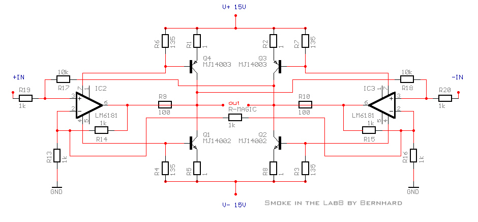
My second question is, if in the following circuit it is even possible that one transistor turns off.
Or does the OP always draw current trough both supply pins, which guarantees that there is always a current through each transistor ?
[
Pan said:
This is a 8W class a amp. To be able to deliver this 1A or 8W into 8ohm in class A, we need to bias the NPN and PNP devices to conduct the full power current (to be precise we need just a tiny bit more to always stay in class A), which is 1A.
By biasing the devices in full class A we adjust until 1A flows thru both devices. What goes into the NPN must pass the PNP as well and nothing goes out thru the hot terminal because we have perfect DC stability on the output.
/Peter
I think it is ok to adjust the idle to >=0,5A.
So both transistors are conducting 0,5A. If we go positive or negative with the signal, one transistor comes >=0A and the other <=1A.
And <=1A flow through the load.
My first question is, how to make the bias "dynamic", so little power is wasted in idle current.
I already got one idea, posted in the Monolithic SuperSymmetry with Current Feedback thread.
My second question is, if in the following circuit it is even possible that one transistor turns off.
Or does the OP always draw current trough both supply pins, which guarantees that there is always a current through each transistor ?
First, we have to note the x2 figure is a theoretical simplification.
The same applies to the x1 figure for the single ended amp. In
the single ended case, we could not swing as much as +/- the
idle current since the transistor would turn off entirely. Rather,
we would have to stay below this value. Also, there is no sharp
limit, except for the case where the transistor turns off entirely.
In practice, we want to limit the swing to a lower value to
improve linearity. Also, there is no sharp distinction between
linear and non-linear behaviour. A transistor gets less and less
linear the larger the current/voltage swing. Operating in class
A does not mysteriously make a transistor linear, it just avoids
the non-linearities due to cross-over that arise in class B and AB
amps. The amp is still more or less linear depending on how
much we swing the current/voltage.
Back to the P-P case then. How much current we can swing
depends on the actual circumstances. Since transistors do not
have a linear gm, it is not so simple that the lower transistor
turn off when the upper reaches twice the idle current. Rather,
the upper transistor reaches twice the idle current well before
the lower one goes down to zero current. In some cases it
may be possible to swing more than +/- twice the idle current
through the load and still stay well away from switching off
any of the transistors. How much we can swing depends depends
on a lot of implementation details, like choice of transistors,
emitter resistors, bias voltage etc. However, the larger the
current swing, the less linear the amp gets, even though we
are still operating in class A.
Note1: I assumed BJTs above. The reasoning should be valid also
for MOSFETs. I'll pass on valves, though (but since there are no
complementary valves, I guess P-P amps will work in a different
way, using transformers).
Note 2: For BJTs, assuming perfectly complemetary devices,
the load current IL is
IL = I0*e^(c*Vbe1) - I0*e^(c*Vbe2)
where
Vbias = Vbe1 + Vbe2
Vbe1 is the Vbe of the upper BJT, Vbe2 is the Vbe of the lower
BJT, Vbias is the bias voltage, I0 is the saturation current for
the BJTs and c = k*T/(q*m) which is constant for a given BJT. Further note, that also these equations are a simplification,
but they help explain what happens in a P-P stage.
Edit: Although attempting to answer the question I do not claim
to be neither enlightened nor expert, so if there are any flaws
in my reasoning, please tell me. However, I made a Spice
simulation to convince myself that it is indeed possible to
trespass the "x2 limit" and still stay in class A.
Actually PP is (as far as I know) the name of a tube circuit where there is no complementary devices.
The common transistor amp is most often called (in litterature) complementary, no?
I would like you in the "2x idle camp" to carefully read my example and tell me where the error is..
/Peter
The common transistor amp is most often called (in litterature) complementary, no?
I would like you in the "2x idle camp" to carefully read my example and tell me where the error is..
/Peter
Pan said:Actually PP is (as far as I know) the name of a tube circuit where there is no complementary devices.
The common transistor amp is most often called (in litterature) complementary, no?
I would like you in the "2x idle camp" to carefully read my example and tell me where the error is..
/Peter
I suppose you refer to post #17. The error seems to be your
claim that the lower transistor turns off when the load receives
a current equal to the idle current, a claim you do not back up
in any way. I cannot see where you get that assumption from.
Even if making the wrong assumption that transisitors are
linear, it would not hold. In that case we would get the idle
current I when the upper transistor conducts 1.5I and the lower
one 0.5I. For real transistors you have to solve the equations
I posted instead.
Edit: Looking back in the thread I see that Werner might have
added somewhat to the confusion by saying that the upper
transistor conducts I+Idelta and the lower one I-Idelta. That
is not true, since it assumes the transistors are linear. We can
approach it to some defree by using emitter resistors, though.
Another who thinks it is 2X bias in PP
Think of it this way ....
For a bias current of 1A with push pull OP :-
[1] Upper device swings about the bias current by +/- 1A,
eg: 0 <-> 1A <-> 2A
[2] Lower device swings about the bias current by -/+ 1A,
eg: 2A <-> 1A <-> 0A
at full +ve excursion the upper is passing 2A with the lower
passing 0A. Therfore 2A must be passing through the load.
Of course, at this point the lower device is not operating in
class A so the peak load current must be slightly less than
2X the bias current.
BTW, it is possible to have a non-complimentary PP.
Dave
Re: Another who thinks it is 2X bias in PP
Just for the record, this also makes the simplifying assumption
that transistors are linear. That is sufficient to understand the
x2 factor, as you show, but not to explain why we could get an
even greater factor than x2 or why we may wish to settle for
a much lower value than x2 to get low distorsion, despite
operating in class A.
DRC said:Think of it this way ....
For a bias current of 1A with push pull OP :-
[1] Upper device swings about the bias current by +/- 1A,
eg: 0 <-> 1A <-> 2A
[2] Lower device swings about the bias current by -/+ 1A,
eg: 2A <-> 1A <-> 0A
at full +ve excursion the upper is passing 2A with the lower
passing 0A. Therfore 2A must be passing through the load.
Of course, at this point the lower device is not operating in
class A so the peak load current must be slightly less than
2X the bias current.
BTW, it is possible to have a non-complimentary PP.
Dave
Just for the record, this also makes the simplifying assumption
that transistors are linear. That is sufficient to understand the
x2 factor, as you show, but not to explain why we could get an
even greater factor than x2 or why we may wish to settle for
a much lower value than x2 to get low distorsion, despite
operating in class A.
Bernhard said:Ok.
I want to built a classA amp, where the idle current increases with the signal.
Does that make sense ?
Some kind of second amp inside the amp which lets the current be high on high signals.
Hi,
This is called “Dynamic Class-A” by Krell. But behold, although you remove the cross-over distortion you get back a very non-linear output stage that generates a lot of intermodulation products. You need a fair amount of feedback to get rid of that.
Main advantage of classic full class-A is that you get very very low levels of distortion at low and moderate output levels. Distortion rises as output level rises. The disadvatage is a lot of heat and a high energy bill. In a class-B you get relatively high distortion at low output levels and distortion lowers at higher output levels. It is obvious that at low domestic levels distortion become more noticable then.
Cheers
Pjotr said:
Hi,
This is called “Dynamic Class-A” by Krell...
The dynamic bias Class A amplifier was (I believe) patented in the 70's by Mr. Pass. He implemented this feature in his first ever amplifier offering from Threshold, the 800A.
Rodd Yamashita
If memory serves me correctly, Krell calls their version "plateau
bias". There is also Mark Levinson's "adaptive bias"
www.madrigal.com/adaptivebias.html
Edit: It seems the link only takes one to the home page. Click
"Madrigal library" and the article can be found under "technical
articles".
bias". There is also Mark Levinson's "adaptive bias"
www.madrigal.com/adaptivebias.html
Edit: It seems the link only takes one to the home page. Click
"Madrigal library" and the article can be found under "technical
articles".
Addendum: It seems the system currently used by Krell is
called "sustained plateau bias III" and is computer controlled:
http://www.krellonline.com/pdf/KRELL_FLB.pdf
http://www.northamptonaudio.com/Krell/krellinfo.htm
called "sustained plateau bias III" and is computer controlled:
http://www.krellonline.com/pdf/KRELL_FLB.pdf
http://www.northamptonaudio.com/Krell/krellinfo.htm
- Status
- Not open for further replies.
- Home
- Amplifiers
- Solid State
- ClassA question for the enlightened...