"No, it can't be tiny. It will dissipate (I^2)*Rp. For best power transfer RL should be equal to Rp, i.e. it will dissipate power equal to output one, otherwise toobs will see variable anode voltages."
The tube does not passively depend on it's Rp to conduct the current while at constant plate voltage, it's grids are actively driving the tube's Gm to provide the load/signal required current (feedback controlled). A pentode works just fine and has excellent PSRR due to its very high Rp. This high Rp is what allows the amplifier to ignore glitches, errors etc from the SS amp.
Yes, true, the power dissipation is not tiny just because the correction output signals may be tiny. But this is due to the effect of using a tube which must have a minimum B+ of hundreds of volts. The tube amp does however at least operate at its idle power always (well assuming tiny corrections). But then a class A amp dissipates the same power all the time anyway, so no savings to be expected, other than using small tubes for a 10 Watt amp. rather than big ones for a 100 Watt amp.
"So, if we don't need push-pull class A amp and go with a linearized one single ended Georges' design is the most elegant version of your approach: it eliminates an output tranny from your equation."
Well, I agree on not needing a P-P tube amp here, a SE one will do just fine also. But I don't see where you find the OT xfmr going away unless one is going to operate it in OTL mode. And OTL is horribly power wasting. We still need an OT to get efficiency from the tube(s). Unless you are thinking the Berning impedance converter idea.
Don
smoking-amp said:
"So, if we don't need push-pull class A amp and go with a linearized one single ended Georges' design is the most elegant version of your approach: it eliminates an output tranny from your equation."
Well, I agree on not needing a P-P tube amp here, a SE one will do just fine also. But I don't see where you find the OT xfmr going away unless one is going to operate it in OTL mode. And OTL is horribly power wasting. We still need an OT to get efficiency from the tube(s). Unless you are thinking the Berning impedance converter idea.
It is going away from anode-cathode voltage stabilizing network in George's case.
smoking-amp said:"It is going away from anode-cathode voltage stabilizing network in George's case."
I'm not following your meaning on this one. Do you mean using a cathode follower, but without constant anode-cathode voltage? How does this solve the output transformer issue?
Don
I mean compensating anode voltage directly instead of through an output tranny.
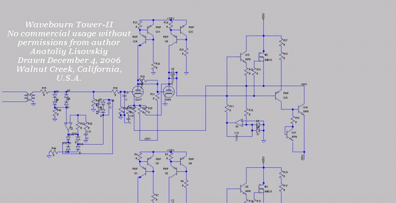
Wavebourn said:I am going to try my Wavebourn's version of a Smocking Amp.

C1 and R1 needed for stability (to prevent oscillations)
Output power from a SE amp that equals to max plate dissipation is an interesting idea.
Oh, I get it now.
The SS amp does low frequencies primarily, and the SE tube amp does high frequency corrections thru a tiny xfmr.
Should work. But don't expect to get SE sound out of it because the low frequency second harmonics won't get generated in the SS amp unless it's design badly.
Vicor makes just such a module that you can buy for removing ripple from power supplies. It has a small amplifier and HF xfmr in a small module that puts in negative ripple to cancel out the original. They call it an "active ripple attenuator".
Don
smoking-amp said:Oh, I get it now.
The SS amp does low frequencies primarily, and the SE tube amp does high frequency corrections thru a tiny xfmr.
Should work. But don't expect to get SE sound out of it because the low frequency second harmonics won't get generated in the SS amp unless it's design badly.
It's because of "tiny transformer". Why it needs to be tiny if we speak of less distortions? Let it compensate on the whole range of frequencies! Anyway the compensation in your approach (output in series) will never be ideal because of complex impedance of a real speaker that depends on frequency.
Here is one more version, more "tubey":

"It's because of "tiny transformer". Why it needs to be tiny... "
Well, I thought you had mentioned something about getting rid of the xfmr or using a tiny HF one. But sure, a large one will work for the full frequency range. But it is an air-gapped one for SE.
"Here is one more version, more "tubey":"
Hmmm, but then the output xfmr has to handle the full power, not just error corrections. And it will have to be air-gapped still.
The idea of putting constant voltage across the triode is useful for enhancing PSRR as in George's design, but it causes the triode to operate just like a pentode in common cathode configuration. This means 3/2 power operation with lots of distortion unless it's used in cathode follower mode (as George does use).
So I don't think this is so important as a primary goal. A better goal would be to get the triode to operate at constant current at all times, but variable voltage. This would give lowest distortion in common cathode configuration (MU), and is the more usual configuration for SE amplifiers (well P-P ones too).
So a load compensating modulated current source plate load for the triode would seem more useful. Probably won't save any power though, which was the original design goal for class G or H.
This could either be in a P-P totem pole configuration with a Mosfet on top and tube on the bottom, or a center tapped xfmr with tube on one side and modulated Mosfet current source on the other. Or it could be done in SE mode with a modulated Mosfet current source in parallel with the tube. The last approach however facing the penulty of needing a choke or air-gapped xfmr.
This "solution" was Yundt's solution for the parallel amplifiers case by the way. You can parallel a current output amplifier and voltage output amplifier without them fighting each other. The current amplifier then gets programmed by feedback or design so as to either minimize current variation or zero out current altogether in the voltage amplifier. You do still want to use a clean amplifier for this though.
The usual class D attempts at this suffer from the noise filter on their output reducing their output Z badly. Then the voltage amp has to fight the filter cap., requiring high speed and ultra low Zout again.
We could try putting a class AB (to save power again) SS current output amplifier (Hi Z output) across the tube amp secondary and monitor the return current from the tube amp so as to try and zero it with the SS ampl. Then the tube amp could operate at zero current variation in the tubes for best accuracy. Triodes would be fine in this case, the lower the tube out Z the better.
Don
smoking-amp said:
"Here is one more version, more "tubey":"
Hmmm, but then the output xfmr has to handle the full power, not just error corrections. And it will have to be air-gapped still.
Anyway it has to handle the whole output power if we speak of constant anode voltage. Actually due to high output impedance your tube amp don't correct tiny errors; SS amp supplies a voltage to the tube output stage that delivers the whole output power.
By the way, I am going to try an asymmetrical output stage. i.e. triode and pentode in P-P configuration, but it is the different story...
"Anyway it has to handle the whole output power if we speak of constant anode voltage. Actually due to high output impedance your tube amp don't correct tiny errors; SS amp supplies a voltage to the tube output stage that delivers the whole output power."
Well the SS amp is supplying power, since they are in series. The SS errors just get "ignored" by the tube amp, showing up as tiny variations in the plate to cathode voltages on the pentodes (so no effect).
"By the way, I am going to try an asymmetrical output stage. i.e. triode and pentode in P-P configuration, but it is the different story..."
I suspect this will give you something close to SE sound. Are you going to supply complementary drive to the pentode or just use it as a CCS?
Here is a link to the parallel amplifier approach I just mentioned above:
http://www.diyaudio.com/forums/showthread.php?postid=595103#post595103
I've always thought it would be the best amplifier topology. Better than Technics Class A+. It also does not require any feedback around the tube amp, which is a plus for some FDBK allergenic types. Well, the tube amp does soley determine the output Z (damping factor) since the SS amp does not contribute here. So some feedback may still be useful in the tube amp if its triodes aren't low enough Rp.
It requires two whole amplifiers however, just like the series topology. A much simpler approach is to just put a couple of $2 HV transistors across the output tubes in Sziklai fashion, so they operate at near constant current. (a Hybrid Components amplifier as opposed to the usual grafted on Hybrid output amplifier)
Don
By using a highly efficient buck SMPS (90 - 95%) to supply the plate voltage, and choosing a vacuum tube that can operate linearly at a low plate voltage and relatively high current, some really efficient tube amps can be designed. The constant K-P voltage lowers the distortion too. A typical SE tube amp has a plate efficiency in the 5 to 15% range. The theoretical maximum for a class A1 amp is 33%. I have measured 55% on one of my modulated designs.
One of the first experiments I did was to test a bunch of power tubes to find ones that could pass high currents at low voltages and do so in a linear manner. Many tubes that I expected to work just wouldn't cut it but a few can work quite well at voltages below 100 volts. My old friend the 6LW6 can deliver up to 650 mA at 100 volts. A 6336A can do 200 mA at 50 volts, 350 mA at 75 volts, and 500 mA at 100 volts. The venerable 6AS7 can do 175 mA at 50 volts and 300 mA at 75 volts but is not as linear as the other two tubes. A 5998A or 7236 works well too.
I also tried several other output topologies, but none worked as well as the simple cathode follower.
Look at the Nelson Pass Aleph amp and think about using a tube for the bottom device. The top device is a modulated mosfet CCS, and the output comes off of the plate using a capacitor and a non gapped OPT as in a parafeed amp with the CCS in place of the choke. This works (I built one), and sounds quite good, but the efficiency is very low, even worse than a normal SE amp. If you want a P-P amp, build two of these drive them with a phase splitter and wire the OPT across the two outputs (didn't try it though). I am planning a monster P-P amp using cathode followers at the 200 WPC power level.
I also attempted to eliminate the need for a gapped OPT in the typical SE amp design. The usual choke and cap parefeed arangement works, but doesn't save and size or weight. You can replace the choke with a CCS, but you give up the OPT's inductive swing capability. To compensate the voltage across the CCS must be increased by as much as the expected output voltage. This is burned up in the CCS as heat, killing efficiency. So what to do? Modulate the voltage source to the CCS so the voltage across the CCS stays constant and low.
Where does this end. I built a cathode follower with its plate voltage modulated to keep 75 volts across the tube. The DC cathode load is a CCS which is connected to another modulated voltage source to keep the voltage across the solid state CCS constant at 15 volts. With 90 volts across the output stage and 300 mA of current the dissipation is 27 watts. Output power is over 25 watts with a 600 ohm load. This technology could be used to develop an SE OTL amp that doesn't melt. (its on my list)
It should be noted that I thought up several schemes for "connecting" tube amps and "digital amps" or digitally modulated power supplies. I went through at least 50 simulations that showed some promise, but building actual working hardware is a different matter entirely. I have a large pile of toasted mosfets, melted switch inductors, a couple of exploded caps, one blown tube, and about a dozen circuits that I just gave up on. It all sounds easy when drawn on the back of a napkin (or debated in a forum thread).
One of the first experiments I did was to test a bunch of power tubes to find ones that could pass high currents at low voltages and do so in a linear manner. Many tubes that I expected to work just wouldn't cut it but a few can work quite well at voltages below 100 volts. My old friend the 6LW6 can deliver up to 650 mA at 100 volts. A 6336A can do 200 mA at 50 volts, 350 mA at 75 volts, and 500 mA at 100 volts. The venerable 6AS7 can do 175 mA at 50 volts and 300 mA at 75 volts but is not as linear as the other two tubes. A 5998A or 7236 works well too.
I also tried several other output topologies, but none worked as well as the simple cathode follower.
So a load compensating modulated current source plate load for the triode would seem more useful. Probably won't save any power though, which was the original design goal for class G or H.
Look at the Nelson Pass Aleph amp and think about using a tube for the bottom device. The top device is a modulated mosfet CCS, and the output comes off of the plate using a capacitor and a non gapped OPT as in a parafeed amp with the CCS in place of the choke. This works (I built one), and sounds quite good, but the efficiency is very low, even worse than a normal SE amp. If you want a P-P amp, build two of these drive them with a phase splitter and wire the OPT across the two outputs (didn't try it though). I am planning a monster P-P amp using cathode followers at the 200 WPC power level.
I also attempted to eliminate the need for a gapped OPT in the typical SE amp design. The usual choke and cap parefeed arangement works, but doesn't save and size or weight. You can replace the choke with a CCS, but you give up the OPT's inductive swing capability. To compensate the voltage across the CCS must be increased by as much as the expected output voltage. This is burned up in the CCS as heat, killing efficiency. So what to do? Modulate the voltage source to the CCS so the voltage across the CCS stays constant and low.
Where does this end. I built a cathode follower with its plate voltage modulated to keep 75 volts across the tube. The DC cathode load is a CCS which is connected to another modulated voltage source to keep the voltage across the solid state CCS constant at 15 volts. With 90 volts across the output stage and 300 mA of current the dissipation is 27 watts. Output power is over 25 watts with a 600 ohm load. This technology could be used to develop an SE OTL amp that doesn't melt. (its on my list)
It should be noted that I thought up several schemes for "connecting" tube amps and "digital amps" or digitally modulated power supplies. I went through at least 50 simulations that showed some promise, but building actual working hardware is a different matter entirely. I have a large pile of toasted mosfets, melted switch inductors, a couple of exploded caps, one blown tube, and about a dozen circuits that I just gave up on. It all sounds easy when drawn on the back of a napkin (or debated in a forum thread).
By the way, I am going to try an asymmetrical output stage. i.e. triode and pentode in P-P configuration, but it is the different story...
Been there, built that. It was a little guy for use as a guitar amp. 6V6 on one side, 6EM7 on the other side. Same Schumaker P-P OPT that you are using in one of your amps. I put "Master Gain" pots in each drive path so that the drive to each tube could be individually adjusted. Each output tube could also be switched off using a switch in series with the cathode resistor. I never tested it for suitability in HiFi applications, but it could be adjusted for a lot of cool guitar sounds. The 6EM7 side by itself had a clean tone to it, and it didn't seem to matter if the 6V6 was on or not. The 6V6 had a "Champ" sound to it, but the 6EM7 had to be switched off to get the amp to really scream. Some of the sounds that could me made using both tubes were really unique.
I only had this amp for about a week, including the weekend that I built it. I thought of all sorts of neat experiments that I wanted to try, but didn't have time. This amp was sold and I never made another one. I want to try this again some day, and maybe a dissimilar pentode pair.
Hi George,
"The constant K-P voltage lowers the distortion too."
Yes, for cathode follower mode as you are using. I should have clarified earlier, when I was talking about increased distortion with constant voltage, that this was meant for common cathode mode.
"Look at the Nelson Pass Aleph amp and think about using a tube for the bottom device."
Yes, I did a while ago. I vaguely recall that he measured the output current to modulate the CCS. I think it may be simpler to just monitor the other driven device current (well at least for class A anyway). Been a while, have to look again.
"This works (I built one), and sounds quite good, but the efficiency is very low, even worse than a normal SE amp."
Hmmm, surprising. I would expect a complementary modulated current source to improve efficiency over plain class A. But it depends on biasing too.
"Modulate the voltage source to the CCS so the voltage across the CCS stays constant and low. "
Yes, this should improve efficiency considerably assuming the modulated voltage source is efficient. And the buck converter should be.
I had suggested such a thing once for another reason, for improving the McIntosh bootstraps back to the driver tube plate loads. This was to remove the linearity degrading positive feeback in that case without reducing the drive levels significantly. This is an idea that should be considered more often, especially with DN2450's etc. available.
"It should be noted that I thought up several schemes for "connecting" tube amps and "digital amps" or digitally modulated power supplies. I went through at least 50 simulations that showed some promise, but building actual working hardware is a different matter entirely. I have a large pile of toasted mosfets, melted switch inductors, a couple of exploded caps, one blown tube, and about a dozen circuits that I just gave up on. It all sounds easy when drawn on the back of a napkin (or debated in a forum thread)."
Duly noted with full respect. This is why I always try to find some simple approach to get near enough to the sought after result. Complicated stuff develops too many variables, often resulting in smoke and flames. I particularly hate to calculate things out accurately, preferring to just adjust parts after a few SWAGs in the dark. This often results in burned resistors or worse. This of course gets impractical with complex circuits. Also explains why I use $0.50 TV tubes for prototyping.
Don
smoking-amp said:
Well the SS amp is supplying power, since they are in series. The SS errors just get "ignored" by the tube amp, showing up as tiny variations in the plate to cathode voltages on the pentodes (so no effect).
They can't be ignored by a load since tube amp has no infinite output resistance. Ohm's law in action.
smoking-amp said:
"Modulate the voltage source to the CCS so the voltage across the CCS stays constant and low. "
Yes, this should improve efficiency considerably assuming the modulated voltage source is efficient. And the buck converter should be.
I had suggested such a thing once for another reason, for improving the McIntosh bootstraps back to the driver tube plate loads. This was to remove the linearity degrading positive feeback in that case without reducing the drive levels significantly. This is an idea that should be considered more often, especially with DN2450's etc. available.
This idea was implemented in several designs, like this one:
tubelab.com said:
Been there, built that. It was a little guy for use as a guitar amp. 6V6 on one side, 6EM7 on the other side. Same Schumaker P-P OPT that you are using in one of your amps. I put "Master Gain" pots in each drive path so that the drive to each tube could be individually adjusted. Each output tube could also be switched off using a switch in series with the cathode resistor. I never tested it for suitability in HiFi applications, but it could be adjusted for a lot of cool guitar sounds. The 6EM7 side by itself had a clean tone to it, and it didn't seem to matter if the 6V6 was on or not. The 6V6 had a "Champ" sound to it, but the 6EM7 had to be switched off to get the amp to really scream. Some of the sounds that could me made using both tubes were really unique.
I only had this amp for about a week, including the weekend that I built it. I thought of all sorts of neat experiments that I wanted to try, but didn't have time. This amp was sold and I never made another one. I want to try this again some day, and maybe a dissimilar pentode pair.
I'm seriously thinking of such triode-pentode design after a tremendous success with transistor voltage follower loaded on a voltage to current converter (you call it modulated CCS, right?)
But in this case it will be a triode loaded on a pentode. Except such an advantage like SE triode character it will use smaller and faster PP transformer than needed for a SE amp of such quality, plus some extra power from a pentode side...
Imagine a Concertina splitter with cathode directly coupled with triode's grid; a trimpot in anode and a capacitor from anode to pentode's grid.
I particularly hate to calculate things out accurately, preferring to just adjust parts after a few SWAGs in the dark. This often results in burned resistors or worse. This of course gets impractical with complex circuits. Also explains why I use $0.50 TV tubes for prototyping.
These have been my design methods for years. I have recently adopted the "model it in LTspice" method to weed out the stupid ideas and get first pass SWAGs at the component values before graduating to the toasted parts stage of development.
See this thread for a picture of an all tube version of a modulated B+ amp that passed the simulation stage, but vented the magic smoke when tested in the real world.
http://www.diyaudio.com/forums/showthread.php?s=&threadid=114021
- Status
- This old topic is closed. If you want to reopen this topic, contact a moderator using the "Report Post" button.
- Home
- Amplifiers
- Tubes / Valves
- Class-g / class-h