Hi everyone,
Tracking Rails Circuitry is quite expensive to implement & yet more difficult is to predict its reliability when mains voltage is constantly varying when powered from generators. ,...I would rather choose to go for Class-D solutions for more control over power and with highest efficiency in low cost budget.....yet good performance....
K a n w a r
I think that it's not so hard to track the music signal with the power supply rails... Consider a unregulated DC-DC converter in order to get the right voltage rails, isolated and with some overvoltage (required for proper current rise slope).
Then consider buck circuits with small output capacitors (just for ripple smoothing) and average current control loops for each one... In these circumstances duty cycle may change from 0% to 100% in very few cycles so 100Khz or 200Khz may do as a switching frequency. Remember that perfect tracking is not required.
I don't feel like starting a new project now, but I will do soon... Also, I want to develop a 12V to 230V inverter capable of powering electric tools and coping with the start-up of SMPS and applications that rectify mains without stressing the switches, so such an output stage will have to behave much like a buck converter with current limiting.
Hello!
Why do we need 1MHz switching frequency? One of my friend designed a Class-D amplifier, which is switching at a couple houndred kHz only. about 250-300kHz.
If we (or anybody, who wants to use a tracking supplied amp) have to design such a fast Buck-regulator, to track a 20kHz sine-wave, why don't we drop the linear amplifier, and connect the speaker directly to that switching regulator?") (ofcource some modifications are needed on the switching regulator, in this case)
(ofcource some modifications are needed on the switching regulator, in this case)
Another idea: If a very-very fast switching regulator needed, then a 2phase regulator can be used.
My electronic-teacher at the high school made a 2phase digital amplifier. Each phases were running at 400kHz,
This thread is getting more and more interesting!
Why do we need 1MHz switching frequency? One of my friend designed a Class-D amplifier, which is switching at a couple houndred kHz only. about 250-300kHz.
If we (or anybody, who wants to use a tracking supplied amp) have to design such a fast Buck-regulator, to track a 20kHz sine-wave, why don't we drop the linear amplifier, and connect the speaker directly to that switching regulator?
(ofcource some modifications are needed on the switching regulator, in this case)Another idea: If a very-very fast switching regulator needed, then a 2phase regulator can be used.
My electronic-teacher at the high school made a 2phase digital amplifier. Each phases were running at 400kHz,
This thread is getting more and more interesting!
This thread is getting more and more interesting!
...... and as soon as it reaches the state "really interesting" it can be moved to the class-d forum !!!
Regards
Charles
One of my friend designed a Class-D amplifier, which is switching at a couple houndred kHz only. about 250-300kHz
Danko, this is not class D. And it's not about the Amp.
It's about building a tracking supply that can be added to an existing class B amp without modifying the amp.
I've simulated a tracking PS at 200KHz pwm, and it's too slow to respond to the worst-case scenario (large 20KHz burst) I described. I clips the first cycle of the burst.
subwo1 has seen similer speed issues when modelling.
I suspect noone would hear distortion if one of 100 cycles of a sound are clipped, and such sounds never exist in music anyways.
Although class D is nice, it's taken me over 6 months to design and build a class D amp, and I never quite got the distortion at high frequencies under control, so I relegated this amp to the sub-woofer realm. Meanwhile I can build a class B in a week and debugging it is no headache.
Eva, then the question remains the following:
Let's say we stick with 100-200KHz PWM and don't worry about perfection in the specs.
Can we modulate the entire rail of a power amp between 10V and 60V (including the power to the low-level front end), or do we absolutely need to gain access to the output transistor rails? (I'm trying to not modify the amp-- what if you wanted to do this to an LM3886 chip--no access to low-level supply).
The low level circuitry should theoretically have a high PSRR (maybe 100dB) and not care about its rails so long as they don't clip, but I'm wondering if in some amp designs there may exist some (unwanted) gain dependence on rail voltage.
(one physics professor once said every amplifier can be a voltage-controlled amplifier if you look hard enough at it).
Andy
This is definitely something worth looking at:
If a class D amp uses an SMPS to convert Line voltage at 120Hz ripple to smooth voltage (by using an error signal to switch it on and off), then uses another circuit to convert smooth DC to sound (again-by switching it on-and-off), this, logically seems redundant.
Why not switch the Line Voltage directly to the speaker?
If you can properly combine the two error signals (line regulation + sound reproduction) into one, you've got it made with just one switcher. Commercial makers should like the material savings realized.
A tracking SMPS is essentially the same thing. If You connect a speaker to the output of an audio-tracking SMPS, you should hear you music quite well. All you need to do is refine the error signal loop to eliminate the distortion.
Andy
why don't we drop the linear amplifier, and connect the speaker directly to that switching regulator?
If a class D amp uses an SMPS to convert Line voltage at 120Hz ripple to smooth voltage (by using an error signal to switch it on and off), then uses another circuit to convert smooth DC to sound (again-by switching it on-and-off), this, logically seems redundant.
Why not switch the Line Voltage directly to the speaker?
If you can properly combine the two error signals (line regulation + sound reproduction) into one, you've got it made with just one switcher. Commercial makers should like the material savings realized.
A tracking SMPS is essentially the same thing. If You connect a speaker to the output of an audio-tracking SMPS, you should hear you music quite well. All you need to do is refine the error signal loop to eliminate the distortion.
Andy
Hi Everyone
I think the links below should be kept somewhere in an easy to find place on the forum, for everyone's reference, because I'm sure querries about Alab products may arise again in the future. Anyone looking at the Alab website needs to also see this stuff.
LabGruppen:
http://www.labgruppen.com/
Class TD:
http://www.labgruppen.com/Files/TechNotes/ClassTD_Technote_9.pdf
MLS switch:
http://www.labgruppen.com/Files/TechNotes/MLS-switch_Technical_note_02-11.pdf
QSC amps:
http://www.qscaudio.com/products/amps/powerlight2/powerlight2.htm
Yamaha class H:
http://www.yamahaproaudio.com/reviews/special/eeengine/
---------------------
I think you may upset the chip-amp building community if you mention SMPS and the LM3886 in the same sentence. They are avid proponents of the "snubberized" power supply.
Joseph
I think the links below should be kept somewhere in an easy to find place on the forum, for everyone's reference, because I'm sure querries about Alab products may arise again in the future. Anyone looking at the Alab website needs to also see this stuff.
LabGruppen:
http://www.labgruppen.com/
Class TD:
http://www.labgruppen.com/Files/TechNotes/ClassTD_Technote_9.pdf
MLS switch:
http://www.labgruppen.com/Files/TechNotes/MLS-switch_Technical_note_02-11.pdf
QSC amps:
http://www.qscaudio.com/products/amps/powerlight2/powerlight2.htm
Yamaha class H:
http://www.yamahaproaudio.com/reviews/special/eeengine/
---------------------
what if you wanted to do this to an LM3886 chip--no access to low-level supply
I think you may upset the chip-amp building community if you mention SMPS and the LM3886 in the same sentence. They are avid proponents of the "snubberized" power supply.
Joseph
I think he's fully aware of what he's attaching.
Now that his bluff has been uncovered, he's trying to dissipate the heat by planting confusion.
The above posts are not meant to provide an understanding -- just to throw up some chaff.
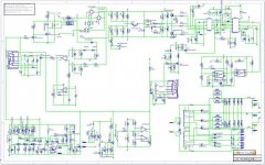
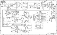
The schematics attached, clearly show that the Alab design is inferior to the originals.
Now that his bluff has been uncovered, he's trying to dissipate the heat by planting confusion.
The above posts are not meant to provide an understanding -- just to throw up some chaff.
The schematics attached, clearly show that the Alab design is inferior to the originals.

HI Workhorse
Pls. show sch. for labgrupen
TD-TECH Series by alab we use Bash audio technology
this link http://www.bashaudio.com/images/stabp01.pdf
Pls. show sch. for labgrupen
TD-TECH Series by alab we use Bash audio technology
this link http://www.bashaudio.com/images/stabp01.pdf
Hi All
new desing class D amp and hi power use Damped Ternary Modulation by apogee chip but same Class I by crown we can't copy crown but same Tecnology
this link http://www.alab-pro.com/index.php?lay=show&ac=article&Id=188967&Ntype=3
new desing class D amp and hi power use Damped Ternary Modulation by apogee chip but same Class I by crown we can't copy crown but same Tecnology
this link http://www.alab-pro.com/index.php?lay=show&ac=article&Id=188967&Ntype=3
He does not seem to understand English properly, otherwise he would notice that we are fully aware of the scam
Also, that thing called DDX is just class BD. It's ideally suited for battery powered boom-boxes and the alike because it certainly extends battery life a bit. However, that modulation scheme produces the highest distortion, quantization, noise and EMI for the smallest audio signals and improves gradually as signal amplitude increases, while conventional class D provides the best precision in the critical low signal range and only becomes worse as the output approaches clipping.
Also, that thing called DDX is just class BD. It's ideally suited for battery powered boom-boxes and the alike because it certainly extends battery life a bit. However, that modulation scheme produces the highest distortion, quantization, noise and EMI for the smallest audio signals and improves gradually as signal amplitude increases, while conventional class D provides the best precision in the critical low signal range and only becomes worse as the output approaches clipping.
Hi Folks,
Mr. Alabpro says he doesnot "COPY" but uses "SAME" Technology....Then what this term should be called.....
The Front panel View of Alabpro and LABGruppen Amps are very much the same....
, even the heatsinks and PCB layout are also same....
He doesnot copy but uses same technology....
Mr. Alabpro says he doesnot "COPY" but uses "SAME" Technology....Then what this term should be called.....
The Front panel View of Alabpro and LABGruppen Amps are very much the same....
, even the heatsinks and PCB layout are also same....
He doesnot copy but uses same technology....
Sonic T amp...
Hi,
"The TA2024 operates by generating a high frequency switching signal based on the audio input.
This signal is sent through a low-pass filter (external to the Tripath amplifier) that recovers an
amplified version of the audio input. The frequency of the switching pattern is spread spectrum
and typically varies between 100kHz and 1.0MHz, which is well above the 20Hz – 20kHz audio
band. The pattern itself does not alter or distort the audio input signal but it does introduce some
inaudible components." http://www.tripath.com/downloads/TA2024.pdf
There is lots of decoupling on the supply rails. Is the 'audio' switching signal also dumped onto the voltage supply pins ?
20hz to 100khz, and 20khz to 1.0Mhz by my calculations means 500X to create the switching frequency.
Would it be worth designing a tracking SMPS for the Sonic T amp?
Looking at the charts I think I can see that the low level performance won't be upto much.
- Status
- This old topic is closed. If you want to reopen this topic, contact a moderator using the "Report Post" button.
- Home
- Amplifiers
- Power Supplies
- Class Evolution-Modulating SMPS output to track audio signal