So far I've been too nervous about using spice since I have no experience with it.
James
Download the free (cut-down) version of TINA spice from the Texas Instruments web site, which will allow you to plot the FR and transient analysis of your output filter. It has a very user-friendly interface, unlike the horrendous UI of the (fully featured) LT Spice. LT Spice is very powerful, but life is too short to put up with a UI that looks like something from a UNIX system in the 1980s!
As has been mentioned earlier: don't use ceramic X7R surface-mount caps (even lots in parallel) in the output filter. I did this years ago, and found (even with a post-filter NFB design) that the distortion was still approx 3X as high as with through-hole film capacitors. With pre-filter NFB, the distortion change may be even more.
Ok, thanks for the help. I'll try your suggestion.
I've contacted Sure about this problem and their only suggestion was to turn the input sensitivity to low. This doesn't solve the breakup or distortion problems. I guest it's just a poorly designed amp. I have some other Tri-2050 Sure amps and they work pretty well even without mods.
Bridging the TDA7498E
Hello Trevor,
I noted in your very detailed post that you talked about bridging the output. I am using the 7498 in a different application then audio.... and I see how to parallel the two outputs but not how to bridge them. At the moment the outputs are going to a toroid transformer with 10 turns primary (two 5 turns actually) and 60 turns secondary. I am using 24 DC for the power. Also running it at 22-28kHz. I have changed the filter cap to different value to allow it to run nicely at these frequencies. I have also removed the inductors from one of the outputs since they are in parallel and I did not see any reason to keep them there. I am testing using the TDA7498E demo board for this.
The manufacture does not specifically state that you can bridge these amps, only parallel them.
Do have any experience with bridging them and if so how to do it safely?
Thanks
The manufacture does not specifically state that you can bridge these amps, only parallel them.
Do have any experience with bridging them and if so how to do it safely?
Thanks
They (hopefully) specifically state that you cannot bridge this chip, only parallel connect it. This chip is internally bridged. You cannot bridge an amp that is already bridged.
Bridged and paralleled amplifiers - Wikipedia, the free encyclopedia
I never read the definition till now.
I never read the definition till now.
I would have thought my minimal network cost little more than a decent EMI snubber ") And yes, 60V p-p of 200KHz EMI floating around is sure to get Aunt Nellie feeling very poorly indeed when she visits you Additionally, any stray capacitance is going to place a huge load on the output switchers. However, if you want to take short-cuts, the inductors and capacitors which SURE install at the factory work well enough to 150Hz, and will certainly snub the EMI pretty well Why not just leave them in place?
And yes, 60V p-p of 200KHz EMI floating around is sure to get Aunt Nellie feeling very poorly indeed when she visits you Additionally, any stray capacitance is going to place a huge load on the output switchers. However, if you want to take short-cuts, the inductors and capacitors which SURE install at the factory work well enough to 150Hz, and will certainly snub the EMI pretty well Why not just leave them in place?
As for your question about parallelling outputs, my sense is that you could never get the output switchers synchronized well enough so they didn't fight each other, at least during the switching edges. Alternative solutions are bridging (of course) and replacing the CPU with one of the newer higher-voltage versions. The original TDA7498 work to 39V, but they are getting quite a lot hotter between 32V and 39V, so 36V is a better maximum to pick, I think.
If you really need high voltage, then there are other switching amps which will do a better job, such as the L15D (Ebay for it).
Hope that helps
And yes, 60V p-p of 200KHz EMI floating around is sure to get Aunt Nellie feeling very poorly indeed when she visits you Additionally, any stray capacitance is going to place a huge load on the output switchers. However, if you want to take short-cuts, the inductors and capacitors which SURE install at the factory work well enough to 150Hz, and will certainly snub the EMI pretty well Why not just leave them in place?As for your question about parallelling outputs, my sense is that you could never get the output switchers synchronized well enough so they didn't fight each other, at least during the switching edges. Alternative solutions are bridging (of course) and replacing the CPU with one of the newer higher-voltage versions. The original TDA7498 work to 39V, but they are getting quite a lot hotter between 32V and 39V, so 36V is a better maximum to pick, I think.
If you really need high voltage, then there are other switching amps which will do a better job, such as the L15D (Ebay for it).
Hope that helps
Last edited:
Download the free (cut-down) version of TINA spice from the Texas Instruments web site, which will allow you to plot the FR and transient analysis of your output filter...
You can do more than that!


in the TI test circuit folder! (Doesn't have the 7498 but does have and 311x)
...
The Sure AB32189 / AB32174 / AB34165 manual doesn't have much:
http://www.parts-express.com/pedocs/manuals/320-303-parts-express-manual.pdf
...
Hey ... I just remembered I have one of these!

Upgrade with silmicII 2uf input caps; 1500uf, 50V on each ps side and the SURE vol control.

I'll give your mods a try!
Last edited:
I would have thought my minimal network cost little more than a decent EMI snubber
As for your question about parallelling outputs, my sense is that you could never get the output switchers synchronized well enough so they didn't fight each other, at least during the switching edges. Alternative solutions are bridging (of course) and replacing the CPU with one of the newer higher-voltage versions. The original TDA7498 work to 39V, but they are getting quite a lot hotter between 32V and 39V, so 36V is a better maximum to pick, I think.
If you really need high voltage, then there are other switching amps which will do a better job, such as the L15D (Ebay for it).
Hope that helps
thanks for that reply.
i do not have the 'Sure-board'
I own these two modules:
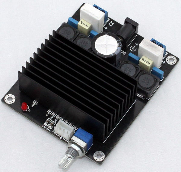
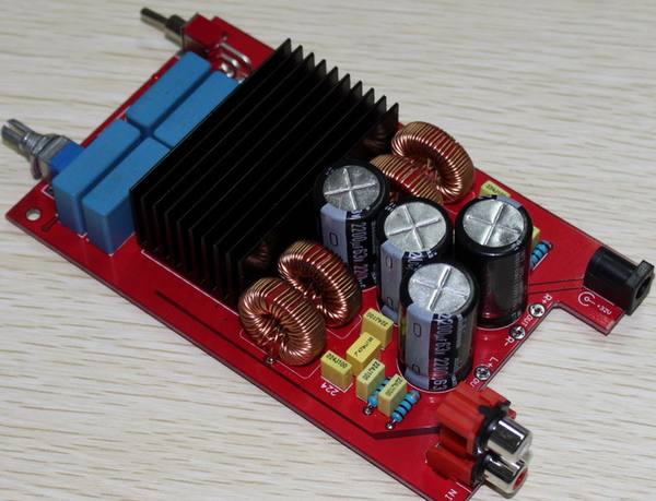
the red board is easy to mod, that's one reason i bought it.
but it sounds ok in stock-form and i lack time to start more projects.
the black board is the cheapest available tda7498-module atm.
i once removed the heatsink and one of the big resistors to see all the traces of the output.
it looks very weird to me:

Class D
I know this thread is old but I wanted to ask TREV if you think you can get the same results from pretty much any current (Sure Electronics) class D such as the very high power ones?
I'm not an electronic engineer, but if they want to see better performance on high frequencies on Class D's dont they need to increase the clock speed of the circuit to sample the wave and operate the output at a much higher resolution.
Not sure about the difference between PCM and PWM but CDs are sampled at 44.1k PCM is that not applicable to PWM??
anyway.. thanks
BTW.. what i'm looking for is class A clarity at Class D power (arent we all)
My only tip in regards to output filter is to use high voltage capacitors.
If someone powers up the amp with no speakers connected the output filter inductor will ring to a high voltage. This can blow the output filter capacitor.
Sound like you have made that bad experience. Could you pls give some details like type of class-damp, pre-/post filter feedback, supply voltage and last but not least specs of caps that blew up.
Sound like you have made that bad experience. Could you pls give some details like type of class-damp, pre-/post filter feedback, supply voltage and last but not least specs of caps that blew up.
It was a irs2092 based design with pre filter feedback.
+/- 45 volts dc supply rails.
I think it was a 470nf 63 volt cap that blew, I now use 250VDC capacitors.
Hello Trevor,
My amp was driven at full volume with 34.5 volt power supply. There was not much heat from filter coils and from heatsinsk. The amps input was from a digital tone control via 1uf x7r capacitor for ac dc coupling. I switch off the amp by taking off its power from poer switch. And the next time I applied the power the amplifier became silent. There is no burn marks or so. I checked the supplies at various pins as per data sheet. The mute pin is permanentaly low as it is being pulled down by tda7498. The VREF pin 34 is also at 0 volt. Vdds is ok.
This is the second amp on whih I m facing the same problem. Please advice.
thank you
- Status
- This old topic is closed. If you want to reopen this topic, contact a moderator using the "Report Post" button.
- Home
- Amplifiers
- Class D
- Class-D Output Filter Designs, SURE TDA7498 as example