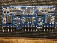
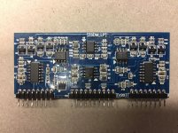
This driver board is from a 6k amp, it's a full range amp class D driver board.
The issue with the amp is one side has Rail to Rail oscillation, and the other side does not. Powers up fine, and clean audio enters the driver board.
The IC's used for driving are IRS21844s, which I see all the time in the typical driver boards for car audio.
This is different, I need to determine what are the 8 pin IC's used (u2, u3 and u4). They work on +5 and - 5 v (Pin 4 and Pin 8)
Any help identifying would be appreciated.
Attachments
Your amplifier is structured like this:
http://sound.whsites.net/articles/pwm-f4b.gif
You have two power stages configured in FULL BRIDGE mode.
Each stage is independent of the other, each one has a high side and a low side.
The amplifier needs both power stages to be able to work properly.
Check whether both power stages have their high side and low side signal.
Probably, only one stage works well, the other no!
In that case, the reasons may be trivial, or even complicated.
You have to check if there is a buffer totem pole on the motherboard, and if yes, make sure that it is working properly.
It could have broken 1 of the two irs21844s or smd transistors above irs21844s.
Thanks Mario,
The issue is that there is no drive to the IRS21844 on the non-functional side (U7 pin 1), but there is on the opposite driver.
I don't have drive into u2 Pin 2, I think I should, because u4 pin 2 does on the working side.
I really need to know what those devices that are defaced are. I swapped IC's u2 & u4 and the results are the same.
Thanks Mario,
The issue is that there is no drive to the IRS21844 on the non-functional side (U7 pin 1), but there is on the opposite driver.
I don't have drive into u2 Pin 2, I think I should, because u4 pin 2 does on the working side.
I really need to know what those devices that are defaced are. I swapped IC's u2 & u4 and the results are the same.
Moving u2 to u4 and vice versa, does the problem move or stay on the same side?
If the problem stays on the same side, you can do these tests:
1- on U5 and U7 pin 1, you have to see the same signal (this test is done with the oscilloscope reference on the negative RCA schield), if you do not see the same signal, check q6, q7, q4 and q10 (if you not know what kind of transistors are, try to zoom well on these components and put the codes or the pictures here, I'll try to help you find the acronyms)
2- intercepts the signal from the U5 and U7 pins 6 and 12, they should be identical, if they are not, you may have problems with the irs21844s and / or totem pole buffer on the motherboard.
Last edited:
Sorry for the delayed response,
I replaced the 1am, 2a and 2d transistors, the irs21844s, same results.
I really need to know what U3 is, the OP amp U2 and U4 signals seem to be feed by u3.
U3
1 +5.00
2 -.29 Audio In
3 0.0
4 -4.9
5 0
6 0
7 -.10 Sawtooth wave form (moves to Audio)
8 +5.0
I replaced the 1am, 2a and 2d transistors, the irs21844s, same results.
I really need to know what U3 is, the OP amp U2 and U4 signals seem to be feed by u3.
U3
1 +5.00
2 -.29 Audio In
3 0.0
4 -4.9
5 0
6 0
7 -.10 Sawtooth wave form (moves to Audio)
8 +5.0
Thanks Mario,
The issue is that there is no drive to the IRS21844 on the non-functional side (U7 pin 1), but there is on the opposite driver.
If you say you moved u2 with u4 and the problem remains the same (on the same side) probably the fault is not U3.
Both irs21844s receive the signal from U3, so if an irs21844s works and the other no, it is likely that the problem lies in the components that are in the middle between irs21844s and u3 or more simply in the IRS21844S.
Unfortunately I do not know u2 and u4 code, but since you have inverted them and you did not find any differences, I think these work fine.
The problem is to look elsewhere.
Try removing defective side irs21844s and check the existing signal on board 1 (no chip) pin.
It's essentially the same.
If you're not getting oscillation, it could be due to a break in the feedback circuit.The feedback is generally via a high-value resistor that connects to the same driver board pin as the input. I don't know if this amp has one for each half of the circuit.
If you're not getting oscillation, it could be due to a break in the feedback circuit.The feedback is generally via a high-value resistor that connects to the same driver board pin as the input. I don't know if this amp has one for each half of the circuit.
I finally got a moment to re visit this amp.
I definitely need to know what u3 is. I believe this is the source of my issue.
I have 5 v on pin1 and pin 8 of u3, they are shorted. I removed the opamp and the opamp has a short from pin 1 to pin 8.
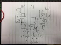
I removed the PCB from the motherboard, and ran +/- 5 volts and ground to the pcb and it acts the same way, I have a saw tooth wave at pin 7 that makes it way up to pin 2 of u4 (through a cap & resistor). That sides works!
An almost identical circuit to the input of u2, only I don't have any drive signal up to u2, pin 2.
I trace backwards through a near identical circuit (cap/resistor), the drive comes from pin1 of u3.
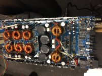
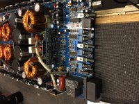
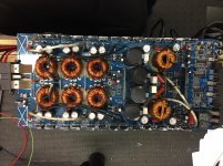
I have posted a few pics, somewhat of a schematic also.
I definitely need to know what u3 is. I believe this is the source of my issue.
I have 5 v on pin1 and pin 8 of u3, they are shorted. I removed the opamp and the opamp has a short from pin 1 to pin 8.
I removed the PCB from the motherboard, and ran +/- 5 volts and ground to the pcb and it acts the same way, I have a saw tooth wave at pin 7 that makes it way up to pin 2 of u4 (through a cap & resistor). That sides works!
An almost identical circuit to the input of u2, only I don't have any drive signal up to u2, pin 2.
I trace backwards through a near identical circuit (cap/resistor), the drive comes from pin1 of u3.
I have posted a few pics, somewhat of a schematic also.
Attachments
FIXED DS18 Pro FR6000.1
Finally got to the root of this problem.
As I thought, U3 was bad, shorted from pin 1 to pin 8. The part number of the IC is LM6643MA, the MA at the end is very important, as it has 2 comparators in it.
Thanks to Perry for spotting what I overlooked. Seems like the people who scratch off the part numbers, didn't scrap the correct number.
")
Finally got to the root of this problem.
As I thought, U3 was bad, shorted from pin 1 to pin 8. The part number of the IC is LM6643MA, the MA at the end is very important, as it has 2 comparators in it.
Thanks to Perry for spotting what I overlooked. Seems like the people who scratch off the part numbers, didn't scrap the correct number.
- Status
- This old topic is closed. If you want to reopen this topic, contact a moderator using the "Report Post" button.
- Home
- General Interest
- Car Audio
- Class D Driver Board Full Range