TK2050 switches at 650KHz
The TK2050 in the Sure 2X100 is switching at 650KHz.well, how big is the sampling frequency you used?It is definitely NOT 2-3 MHZ, right?
Eva wrote:
A minimum pulse-width can be obtained with such a circuit:
class-D amplifier PWM Verstrker SODFAs und D-Amps
But does one really call this sampling ?
Regards
Charles
In my circuit there is no clock, the purpose of sampling is to force a minimum pulse width and prevent bouncing or parasitic self oscillation when the feedback loop becomes open.
It is completely different from how the sampling comparator is used in mentioned Tripath patents...
The TK2050 in the Sure 2X100 is switching at 650KHz.
How did you measured it? Could you please post here some switching waveforms from the prefilter-output of the TK2050?
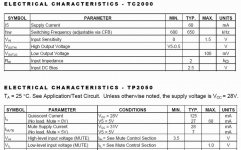
Data sheet
It's stated right there on the data sheet for the TC2000/TK2050 I linked a few posts back and also on any of the Tripath papers discussing filter design. It is also verified while sniffing the relative leakage with an AM radio of the various coil types I have been trying. 630-650Khz and some second harmonic at 1300KHz.How did you measured it? Could you please post here some switching waveforms from the prefilter-output of the TK2050?
Attachments
I remember having read some paper by Tripath about reducing the switching frequency and als improving THD performance by introducing a lowpass pole in the feedback path. You couldn't do this with a classic fixed sampling-rate delta-sigma loop.
I asked Bruno Putzeys about how much he knew about Tripath's topology. He clearrly pointed out that it may all be found in their patents (and I must admit that I have only read a part of them) !
But here is what he wrote:
Regards
Charles
I asked Bruno Putzeys about how much he knew about Tripath's topology. He clearrly pointed out that it may all be found in their patents (and I must admit that I have only read a part of them) !
But here is what he wrote:
Tripath is basically a 3rd order self-oscillating loop. However, Adya Tripathi previously designed switched-capacitor chips so he built the loop using switched-capacitor integrators, clocked at 40MHz. The first pole is continuous-time though, in order to prevent aliasing of switching distortion. So, 1 continuous-time and 2 discrete time integrators. The average switching rate is not synchronous with the 40MHz clock, but the transitions are definitely sampled. The effect is to introduce a form of quantisation noise, and the rather high switching frequency of the class T chips was chosen in order to have enough room above 20kHz to shape this noise into.
Regards
Charles
It's stated right there on the data sheet for the TC2000/TK2050 I linked a few posts back and also on any of the Tripath papers discussing filter design. It is also verified while sniffing the relative leakage with an AM radio of the various coil types I have been trying. 630-650Khz and some second harmonic at 1300KHz.
I asked Bruno Putzeys about how much he knew about Tripath's topology. He clearrly pointed out that it may all be found in their patents (and I must admit that I have only read a part of them) !
But here is what he wrote:
Tripath is basically a 3rd order self-oscillating loop. However, Adya Tripathi previously designed switched-capacitor chips so he built the loop using switched-capacitor integrators, clocked at 40MHz. The first pole is continuous-time though, in order to prevent aliasing of switching distortion. So, 1 continuous-time and 2 discrete time integrators. The average switching rate is not synchronous with the 40MHz clock, but the transitions are definitely sampled. The effect is to introduce a form of quantisation noise, and the rather high switching frequency of the class T chips was chosen in order to have enough room above 20kHz to shape this noise into.
Regards
Charles
LOL! All this time we have talked about the completely different chips/chipsets, which are seem to be implemented with completely different modulation schemes
TA2020, which was pointed in the first post in this thread, even has no any point about some 'typical' switching frequency, and there is no way mentioned, how to adjust it. Whereas TK2050 datasheet says about it clearly (650 kHz, adjustable via capacitor in the feedback network)...
Now I am completely agree, that the TK2050 can be the self oscillating amp (having a lot better parameters in datasheet), whereas TA2020 not at all (switched caps stuff)...
Thanks Charles to clear it!
- Status
- This old topic is closed. If you want to reopen this topic, contact a moderator using the "Report Post" button.
- Home
- Amplifiers
- Class D
- Class D at low volume levels