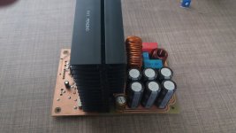
Compared with the initial project started here: Class D amp with 300v mosfets , this one is based on Sic MOSFET transistors:
http://www.rohm.com/web/global/datasheet/SCT3030AL
For gate driver, I use http://www.ti.com/lit/ds/symlink/ucc21521.pdf with simple 18vdc source. Modulator is clocked at 250khz, feedback after the filter, notch at output, for minimum interference with other channels and smps.
Over-current protection uses the RDS(on) of the output MOSFETs as current sensing resistors.
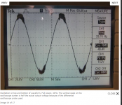
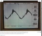
The power supply voltage will be +/- 145 ... +/- 180V, but I chose to test and fine-tune at a lower voltage, +/- 105v with 4 and 8 ohms load, including Chocoholic's hard switching test (load connected to + or -vcc).
In order:
1-top
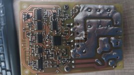
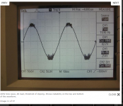
2-bottom
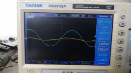
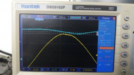
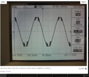
3-residual before and after notch
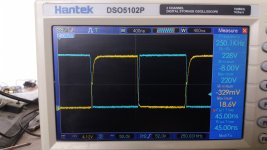
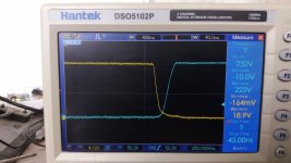
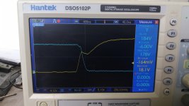
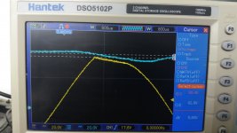
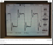
4-Uds, Ugs
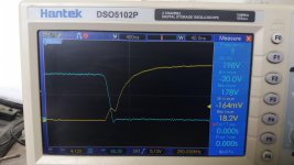
5-Uds up, idle
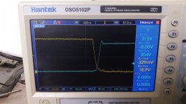
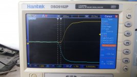
6-Uds up hard sw +vcc 8r load
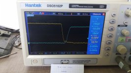
7-Uds up hard sw -vcc 8r load
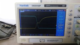
8-Uds down idle
9-Uds down hard sw +vcc 8r load
10-Uds down hard sw -vcc 8r load
http://www.rohm.com/web/global/datasheet/SCT3030AL
For gate driver, I use http://www.ti.com/lit/ds/symlink/ucc21521.pdf with simple 18vdc source. Modulator is clocked at 250khz, feedback after the filter, notch at output, for minimum interference with other channels and smps.
Over-current protection uses the RDS(on) of the output MOSFETs as current sensing resistors.
The power supply voltage will be +/- 145 ... +/- 180V, but I chose to test and fine-tune at a lower voltage, +/- 105v with 4 and 8 ohms load, including Chocoholic's hard switching test (load connected to + or -vcc).
In order:
1-top
2-bottom
3-residual before and after notch
4-Uds, Ugs
5-Uds up, idle
6-Uds up hard sw +vcc 8r load
7-Uds up hard sw -vcc 8r load
8-Uds down idle
9-Uds down hard sw +vcc 8r load
10-Uds down hard sw -vcc 8r load
Attachments
-
 1-top.jpg905.9 KB · Views: 1,106
 -
 2-bottom.jpg761.3 KB · Views: 1,147
 -
 3-rezidual.jpg653.7 KB · Views: 1,060
 -
 4-vds vgs.jpg640 KB · Views: 997
 -
 5-vds up idle.jpg617.4 KB · Views: 969
 -
 6-vds up hard+ 8r.jpg651.6 KB · Views: 264
 -
 7-vds up hard- 8r.jpg713.8 KB · Views: 218
 -
 8-vds down idle.jpg635.1 KB · Views: 202
 -
 9-vds down hard+ 8r.jpg742.3 KB · Views: 201
 -
 10-vds down hard- 8r.jpg709.7 KB · Views: 215
1-lm361 comparator output
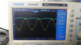
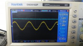
2-50hz sine max 4r load
3-50hz sine clip
4-50hz sine hard clip (with active limiter at input, reference from power sources)
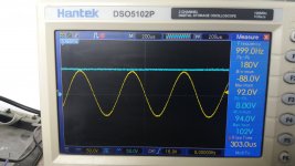
5-1khz sine max
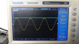
6-10khz sine max
7-10khz sine low
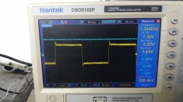
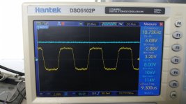
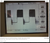
8-1khz square no load
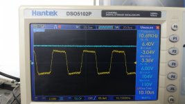
9-1khz square 8r load
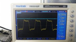
10-1khz square 4r load
2-50hz sine max 4r load
3-50hz sine clip
4-50hz sine hard clip (with active limiter at input, reference from power sources)
5-1khz sine max
6-10khz sine max
7-10khz sine low
8-1khz square no load
9-1khz square 8r load
10-1khz square 4r load
Attachments
-
 11-comparator out.jpg952 KB · Views: 183
 -
 12-50hz sine max.jpg641.7 KB · Views: 162
 -
 13-50hz sine clip.jpg934.1 KB · Views: 153
 -
 14-50hz sine hard clip.jpg972 KB · Views: 117
 -
 15-1khz sine max.jpg959.5 KB · Views: 144
 -
 16-10khz sine max.jpg696.9 KB · Views: 129
 -
 17-10khz sine low.jpg937.1 KB · Views: 134
 -
 18-1k square no load.jpg628 KB · Views: 134
 -
 19-1k square 8r load.jpg918.5 KB · Views: 148
 -
 20-1k square 4r load.jpg701.3 KB · Views: 141
Last edited:
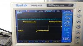
1-10k square 4r load
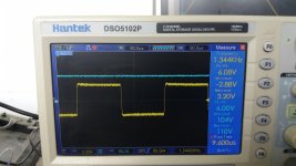
2-10k square 8r load
3-10k square no load
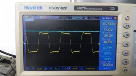
4-10k square no load high voltage
5-video hard switching test with 8r load at +vcc:
YouTube
2-10k square 8r load
3-10k square no load
4-10k square no load high voltage
5-video hard switching test with 8r load at +vcc:
YouTube
Attachments
Last edited:
...glad to see that you are happy with the SiC approach.
I see, you have chosen a moderate switching speed - that's fortunate for EMI,
but of course generates some more losses than theoretically possible.
But somehow you are right, in real implementations the combination of low Qrr and moderate switching speed is often the most healthy trade off.
My congratulation.
I got 2.2mhz switching 84 volts with IRFB4212 mosfets. the high side drivers get hot at that frequency but the output at 20khz at 1v is equivalent to class A. OPA2134 provides the correction signal.
overload capability decreases with frequency.
only reason i am not using class D is the amp goes into a sx-3700 and causes low level noise on FM broadcasts as it is 5" from the tuner.
overload capability decreases with frequency.
only reason i am not using class D is the amp goes into a sx-3700 and causes low level noise on FM broadcasts as it is 5" from the tuner.
Last edited:
- A modulator exists that produces better audio quality while switching frequency is smoothly reduced to <30% towards clipping.
- Hi-Fi audio specs can be obtained from <350khz idle switching.
- You will never be able to use full SiC switching speed with large thru-hole packages and 2-layer PCB.
- SiC MOSFET prices won't go down. Some companies will.
- Industrial scams are like sea waves. A scam is being surfed. Happy surfing.
- I prefer dancing. Making a simple crowd of hundred vibrate. Making the land and building vibrate. Feeling barely warm cheap-MOSFET prototype heatsink.
Last edited:
True. Plus:
The biggest wonders about SiC MOSFET:
- Gate oxide layer requires far more time, energy and precision to be produced, in comparison with Si MOSFET. The layer is not so electrically rugged.
- Electrical switching properties of SiC MOSFET gate are inferior to Si MOSFET: High threshold voltage requires high inductance to control di/dt, which results in high snubber dissipation. High series resistance requires negative drive for faster turn-off, despite high threshold voltage.
- In the long term, new stuff prevails only in fields and usage patterns where it makes more measurable differences for good than for bad. Si LV MOSFET with SiC JFET cascode: The switching and body diode performance of 30V MOSFET extended up to 1200V. Drop-in replacement for MOSFET.
btw: The trick is: nowadays most investors in tech companies do not even know how to measure voltage with a multimeter.
Eve, I understand that you are against the SiC mosfet technology and against the clocked modulator. Nobody forces you to change your mind. But, can you give a constructive advice to improve this amp? I can provide everything you need to know.
I don't read anywhere that Eva is really against it.
Eva's response is just slightly ironic/sarcastic.
But what I do think is that people need to realise which choices and compromises they make and for what reasons.
And that a lot of stuff (especially in the field of audio) can be a result of good marketing instead of fundamental physics.
Still ldoesn't mean you can go for it of course
")
Please note:
- I'm providing feedback because ionutgaga asked me privately to do so.
- He opened a 2nd thread for the same purpose, as 1st one became forgotten.
- His choice is the worst performing type class-D audio modulator implementation.
- His choice is the worst performing type of SiC transistor implementation.
- His work represents no improvement over IGBT and self-oscillating modulator. Cost is 10 times higher.
- I wish I could have so many resources to waste.
- I'm running into difficulties finding a brand interested in technology far better than yours.
- The system got so corrupt that technology no longer matters for many firms. Company hierarchies became sodomite in nature.
- There is an economic crack like 1929's coming soon. Imitators getting higher priority in funding system is the cause.
- I'm starting to consider finding a job in a different sector meanwhile.
Last edited:
-with constructive advices
-It is mentioned in the first post, it has a different name
-so many amplifiers has the same topologies
-what is wrong, and how many correct implementation exists
-20 euro for one sic mosfet
-again, 40 euro for 2 power switches, I wonder ...
-?
-???//
There are many amplifiers on the market with less successful implementations:
PKN Controls XD4000 Amplifier Test Results :: ABELtronics
Funktion-One, FFA F60Q/FFA6004 Amplifier Test Results :: ABELtronics
Attachments
All fixed-frequency modulation brands are imitating each other. Some results are really poor and dirty.
It's not about technology. It's not about specs. It's not about waveforms. These companies won't hire you even if you have better technology at lower cost. They want to keep their structure, with shy engineers cleaning the shoes of selfish executives.
You won't be able to compete in price with something cloned by several dozen factories in China. Innovation was the remaining solution, but innovation requires a company grown by innovation, not by engineers cleaning shoes of executives. Everyone shall clean their own shoes.
Eva, I'm doing this amplifier for personal use, I do not want to sell as a kit or a finished product, and the idea of working at a big company is far from me.
Back in 2005 I have made this amplifier only for personal use, classH 4 tier, only because I can do it: http://www.diyaudio.com/forums/solid-state/84443-class-ab-schematics.html#post984502
Back in 2005 I have made this amplifier only for personal use, classH 4 tier, only because I can do it: http://www.diyaudio.com/forums/solid-state/84443-class-ab-schematics.html#post984502
Last edited:
Member
Joined 2009
Paid Member
Features, in comparison with "king of poor" analog self-oscillating post-filter modulator (quad op-amp, comparator and passives):
- 10~20dB worse SNR. Still worse SNR paralleling all 8 channels.
- Same low-volume THD.
- High-volume THD similar to low-volume. At high volume one is more likely to need overload control, musically sounding.
- Digital input. Do you want accurate overload control? Then the DSP must be built into the amplifier. Do you want negative output resistance, or any other analog signal processing? It is not possible.
- Limited field of application.
- Status
- This old topic is closed. If you want to reopen this topic, contact a moderator using the "Report Post" button.
- Home
- Amplifiers
- Class D
- Class D amplifier using SiC Mosfets