Light Bulbs in PowerAmp2SJ28BC
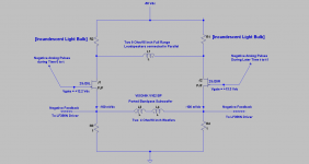
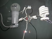
The schematic shows the location of the Incandescent Light Bulbs which were used therein as load resistors to the VFETs; replacing the 8 Ohm/20W non-inductive resistors in the schematic of the previous post. Each pair of light Bulbs was matched for ~identical resistance in a range of current passing through them. The light bulbs which were studied are shown.
1. A standard 100 W/130Vac light bulb
2. The Compact Fluorescent bulb is a salvage and has twin filaments; which match to within ~3% resistance. Wear leather gloves on both hands; because the bulb is fragile [hold by plastic base], and force is used by the other hand to disassemble the spent electronics.
3. The light bulb in the middle is from a spent Xmas light string. A pair was mounted on blown fuses on a fuse holder [Bulb Fuse]. The resultant series connected Fuses make one light bulb.
4. The process of matching light bulbs for resistance follows; e.g, for CFL. Connect the filaments in series, pass a known DC from a variable power supply [I have a 0-20 VDC PSU @ 0.5 A], and measure the voltage drop across the filaments at several current values. Use Ohm's Law to calculate resistance.
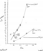
A Tungsten incandescent light bulb is a power resistor; the resistance of which is a function of the current passing through it. The graph shows the relationship between the resultant resistance due to the Direct Current passing through each of the three light bulbs; relative to a standard 8 Ohm power resistor which has a constant resistance. The current ranged between 50-400 mA, and the resistance of the 100 W bulb [for example] varied between 11 and 48 Ohms. Note the appearance of filament Glow at the indicated point of the function.
So what is the influence of the load light bulbs on performance? Next post..
The schematic shows the location of the Incandescent Light Bulbs which were used therein as load resistors to the VFETs; replacing the 8 Ohm/20W non-inductive resistors in the schematic of the previous post. Each pair of light Bulbs was matched for ~identical resistance in a range of current passing through them. The light bulbs which were studied are shown.
1. A standard 100 W/130Vac light bulb
2. The Compact Fluorescent bulb is a salvage and has twin filaments; which match to within ~3% resistance. Wear leather gloves on both hands; because the bulb is fragile [hold by plastic base], and force is used by the other hand to disassemble the spent electronics.
3. The light bulb in the middle is from a spent Xmas light string. A pair was mounted on blown fuses on a fuse holder [Bulb Fuse]. The resultant series connected Fuses make one light bulb.
4. The process of matching light bulbs for resistance follows; e.g, for CFL. Connect the filaments in series, pass a known DC from a variable power supply [I have a 0-20 VDC PSU @ 0.5 A], and measure the voltage drop across the filaments at several current values. Use Ohm's Law to calculate resistance.
A Tungsten incandescent light bulb is a power resistor; the resistance of which is a function of the current passing through it. The graph shows the relationship between the resultant resistance due to the Direct Current passing through each of the three light bulbs; relative to a standard 8 Ohm power resistor which has a constant resistance. The current ranged between 50-400 mA, and the resistance of the 100 W bulb [for example] varied between 11 and 48 Ohms. Note the appearance of filament Glow at the indicated point of the function.
So what is the influence of the load light bulbs on performance? Next post..
Attachments
Subjective Performance Using Light Bulb as load resistors
The attached is a simplified schematic of the power output stage of the AP amplifier using 2SJ28 SITs under discussion in the previous posts. I compared the subjective [music] performance of the "systems" when using 10 Ohm/20W non-inductive resistors versus the Fuse Light Bulbs [previous post] as loads to the SITs. Here's the verdict:
1. The sound of the two systems was different regarding the spectral balance; albeit at a similar clarity and detail.
2. The output stage using the 10 Ohm power resistors had a deeper/forward low end, and the vocals were flat and recessed by comparison.
3. The output stage using the Fuse Light Bulbs had a softer/recessed low end, but the vocal were up-front and lively meaning some spatial dimension.
The following maybe responsible for the sonics. In operation, as the current in the SITs increased due to analog pulse signals, the absolute value of the 10 Ohm load resistance stayed put/constant. By contrast, as the current of the SITs increased, the resistance of the filaments in the bulbs also increased from an idle resistance of ~11 Ohms [faint glow] to upward of 25 Ohms at full brightness.
The light bulbs gave a pulsating light show which ranged from a faint glow to full brightness with a fast rise and fast decay in light output. This reflected the dynamic range of the input signals, and the resultant output power delivered to the loudspeaker. The bulbs appeared to work like a VU meter.
I prefer the light bulbs over the 10 Ohm load resistors for their different sonics, and their ability to protect the SITs when malfunction hits as fuses.
Attachments
Output Transformer for Analog Pulse Power Amp 2SJ28
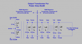
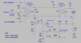
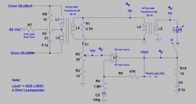
A SIT has a low drain resistance which requires mating/matching it with a low resistance load. The 2012 SIT Nemesis article in First Watt by Mr. Pass [excellent read] talked about a transformer-coupled SIT power output stage. It focused in part on using the proper transformer for best results. The schematic of the transformer under study is attached. It is actually made by using two identical, and off the shelf transformers. The transformers' details are:
1. A Triad Magnetics toroid power transformer [100 VA] named VPT24-4170 has two independent 115 Vac primary windings, and two independent 12 Vac secondary windings
2. With reference to the schematic, and noting transformer #1 on its left, the 12 Vac secondary windings are connected in series [note phase dots], and the primary 115 Vac windings are connected in parallel [note phase dots].
3. The center tap/lead of the secondary windings [now 24 Vac] goes to the -50 Vdc PSU of this amp. The two other out of phase 12 Vac leads go to the drains of the power output 2SJ28 pair.
4. The two 115 Vac primary windings of transformer # 1 are then connected to the two 115 Vac primary windings of transformer #2 [on the right of schematic] which are also connected in parallel.
5. The two 12 Vac secondary windings of transformer#2 are then connected in parallel, and are the power output leads of the power amp.
6. The above five points talked about an equivalent toroid power transformer which has a 24 Vac center tapped primary windings and one secondary 12 Vac winding.
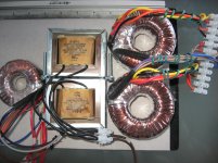
The photo shows 3 compounded power transformers from Triad Magnetics. I listened initially to a compound of the left 25 VA toroid on the left. I liked its sound. I moved on to the 100 VA compound toroid transformer on the right. It sounded great, and had a more open sound. Still both of the low and high VA toroid compounds had a similar sound character. I then moved on to using the metal core F-56X compound in the middle of the photo. F-56X has one 115 Vac primary and a center tapped 25.2 Vac secondary winding [70 VA]. This metal core compound transformer had a different sonic signature than the toroids but sounded fully satisfactory.
The full range loudspeaker was best suited to mate with amp versus a the boxed 3 way I have. I'll do additional listening using the metal core and toroid compounds and report findings.
A SIT has a low drain resistance which requires mating/matching it with a low resistance load. The 2012 SIT Nemesis article in First Watt by Mr. Pass [excellent read] talked about a transformer-coupled SIT power output stage. It focused in part on using the proper transformer for best results. The schematic of the transformer under study is attached. It is actually made by using two identical, and off the shelf transformers. The transformers' details are:
1. A Triad Magnetics toroid power transformer [100 VA] named VPT24-4170 has two independent 115 Vac primary windings, and two independent 12 Vac secondary windings
2. With reference to the schematic, and noting transformer #1 on its left, the 12 Vac secondary windings are connected in series [note phase dots], and the primary 115 Vac windings are connected in parallel [note phase dots].
3. The center tap/lead of the secondary windings [now 24 Vac] goes to the -50 Vdc PSU of this amp. The two other out of phase 12 Vac leads go to the drains of the power output 2SJ28 pair.
4. The two 115 Vac primary windings of transformer # 1 are then connected to the two 115 Vac primary windings of transformer #2 [on the right of schematic] which are also connected in parallel.
5. The two 12 Vac secondary windings of transformer#2 are then connected in parallel, and are the power output leads of the power amp.
6. The above five points talked about an equivalent toroid power transformer which has a 24 Vac center tapped primary windings and one secondary 12 Vac winding.
The photo shows 3 compounded power transformers from Triad Magnetics. I listened initially to a compound of the left 25 VA toroid on the left. I liked its sound. I moved on to the 100 VA compound toroid transformer on the right. It sounded great, and had a more open sound. Still both of the low and high VA toroid compounds had a similar sound character. I then moved on to using the metal core F-56X compound in the middle of the photo. F-56X has one 115 Vac primary and a center tapped 25.2 Vac secondary winding [70 VA]. This metal core compound transformer had a different sonic signature than the toroids but sounded fully satisfactory.
The full range loudspeaker was best suited to mate with amp versus a the boxed 3 way I have. I'll do additional listening using the metal core and toroid compounds and report findings.
Attachments

PowerAmp2SJ28Compound
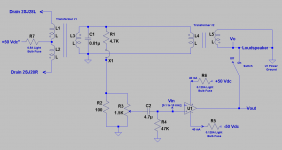
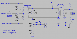
I found myself undecided whether to call the Analog Pulse 2SJ28 power amp understudy a voltage source or a current source amp? I do not know how to determine this theoretically or experimentally. What is the value of the output impedance at the 12 Vac secondary winding of Transformer #2 in the attached left schematic; which the full range loudspeaker sees? Damping is at issue; because this amp does not use overall negative feedback to the input of the precision rectifier.
The attached right schematic shows a viable approach to convert the parent amp to a voltage source amp which has a very low output impedance or a high damping factor.
1. U1 is a non-inverting voltage source power amp of voltage gain = 27 from its schematic. I already have the one depicted which is a salvage 75 W in 8 Ohms.
2. U1 operates in Class AB. Its power output BJTs idle at +/- 40 mA [adjustable].
3. The power rails for U1 are + and - 50 Vdc. The amp module is protected [by me] by using 0.125 A light bulb fuses; one per rail. The 2 light bulbs show a steady orange glow.
4. In operation, the power output of U1 [Vout] is merged with the power output of 2SJ28 [Vo at the 12 Vac secondary of transformer#2] by closing the indicated switch.
5. The inter stage primary [120 Vac] windings of the 2 transformers, act to generate and ground-loop isolate the input signal Vin presented to power amp U1 [0.1 to 10 KHz]. Vin and Vo are highly correlated by transformer #2 action.
6. Vin signal to power amp U1 and it important magnitude is generated as shown, and must be finely adjusted by using the indicated variable pot.
7 Note that Vin, Vout and Vo are AC signals which are in phase.
Here is the simple procedure to operate this compound amp.
1. Open switch at Vout of U1.
2. Use a full-range or a 3-way box loudpeaker as the load
2. Use a 100 Hz sine signal to generate a measurable Vout signal on the scope, and by AC multimeter.
3. Generate Vi and adjust its value with the potentiometer such that the magnitude of Vout of U1 is exactly equal to Vo. Use the AC voltmeter between Vo and Vout to get 0 Vac. The two signals are in phase and have equal amplitudes.
4.Close switch, and merge Vo with Vout. No change in the amplitude of the joint Vo-Vout.
5. The potentiometer adjustment of Vi is final [leave it alone].
6. Repeated steps 1-4 at 1 and 10 KHz. A slight drop in the magnitude of Vo-Vout was observed at 10 KHz; but not at 1 KHz.
This is the outcome and its value on subjective and objective performance. The current which is delivered through the loudspeaker emanated solely from the 2SJ28 amp. This was evidenced by the pulsating 0.5 A light bulb fuse [on transformer#1] from a faint glow at idle to bright. And the the output impedance of the compound amp as seen by the loudspeaker is very low and is attributed to U1 only. Power amp U1 does not do any work; because Vin tracks Vo-Vout continuously. This was evidenced by the steady glow of its 0.125 A power rail light bulb fuses; meaning it was not asked to deliver any current to the load. The power capability of U1 [75 W] is overkill.
I used the full range and also the the 3-way [ADS L-730] to listen to the compound amp. Amazing subjective performance. I found it difficult to turn off this system after 1 hour of music listening.
Attachments
Last edited:
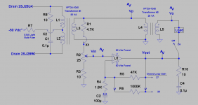
I hope that you review the previous two posts to get back in the groove of this post. The objective of using a power transformer with the 2SJ28s is to mimic the power output stage of a vacuum tube triode. The drains of the 2SJ28s required they mate with the low impedance windings of a power output transformer; meaning its secondary windings. This led me to use two transformers connected as depicted above; which gave a low impedance as seen by the 2SJ28s, and a low impedance as seen by the loudspeaker. I then wondered whether the output of the transformer driving the loudspeaker was a voltage or a current source. This led to using power amp U1 to ensure that the loudspeaker is mostly driven by the VFETs, but loudspeaker damping is managed only by U1. U1 is a sentinel. This is where I am with this design: Please see the attached schematic for the following enhancements and explanation:
1.The Zobel across the drains of the 2SJ28s removed ringing on the AC signals.
2. The input circuits for power amp U1 [4.7 uF, 47 K] are part of it.
3. I showed them [in the previous, and this posts] to highlight their coupling to the new voltage divider circuit which generates Vin.
4. I added sine-wave depictions which clearly say that Transformer#2 provides a positive feedback loop to power amp amp U1.
5. It follows that beyond a certain value of Vin which provides the needed loudspeaker damping, the power amp U1 will oscillate.
6. The rule is to match the amplitude of Vout [from U1] with Vo from transformer #2. One has a bit latitude to make Vout slightly larger in magnitude that Vo.
This amp sounds fully satisfactory. There is a sonic difference between the 2SJ28s' amp operating solo, and aided by power amp U1. The issue of loudspeaker damping is clearly heard, as tightness in the bass region, and a readjustment in spectral balance.
I have two 25 VA Triad Magnetics toroid transformers [VPT24-1040] with windings like those of the two 100 VA toroids already used. I'll use these lower power toroids in a similar application and report the findings.
Attachments
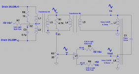
I'd like to show you an application while I still had the two toroids VPT24-4170 [each a 100 VA] connected in the 2SJ28 power amp. I simplified a bit the schematic for clarity. It shows that the loudspeaker load is a dual voice coil woofer of a commercial subwoofer; depicted at its right side. The objective of the utility power amp U1 is like before to shadow or bootstrap Voice Coil #1 by voltage it generated across Voice Coil #2. The extent of bootstrap via U1 voltage source power amp was adjusted as follows:
1. Input frequency was 1 KHz.
2. Drive voice Coil #1.
3. Measure the voltage across Voice Coil #2; not loaded.
4. Match the output voltage of U1 [not connected yet] to that of unloaded Voice Coil #2 by using the pot at U1's input.
5. Connect the power output of U1 to Voice Coil #2.The amplitude of the 1KHz signal before and after bootstrapping did not change.
I thought that both voice coils have identical characteristics. Not so; which is beneficial. At any test frequency, the voltage across Voice Coil #1 was higher in amplitude than that across Voice Coil #2. This difference in the power output voltages, allowed extending the frequency range of this 10" woofer with a piezo driver. The resultant system sounded great. No phase dot is shown for the piezo relative to that of the voice coils which are in phase. One way, the sound is augmented with one particular phase of the piezo, and diminished when reversed. I preferred the augmented full spectrum, and detailed sound.
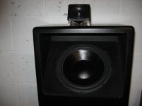
The middle photo shows the subwoofer and its [unattached] piezo driver; which was moved back or forth on the top surface to get best sound.
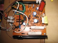
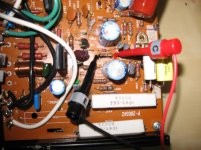
the photo of U1 power amp is on the right. It is from a 1982 vintage Realistic STA 2000D receiver; made in Japan. I blew at one time the power outputs BJTs. I refurbished it. It behaves very well. The maroon component at the top right of the PCB is that 4.7 uF [MPP] which I showed in the previous couple schematics.
1. Input frequency was 1 KHz.
2. Drive voice Coil #1.
3. Measure the voltage across Voice Coil #2; not loaded.
4. Match the output voltage of U1 [not connected yet] to that of unloaded Voice Coil #2 by using the pot at U1's input.
5. Connect the power output of U1 to Voice Coil #2.The amplitude of the 1KHz signal before and after bootstrapping did not change.
I thought that both voice coils have identical characteristics. Not so; which is beneficial. At any test frequency, the voltage across Voice Coil #1 was higher in amplitude than that across Voice Coil #2. This difference in the power output voltages, allowed extending the frequency range of this 10" woofer with a piezo driver. The resultant system sounded great. No phase dot is shown for the piezo relative to that of the voice coils which are in phase. One way, the sound is augmented with one particular phase of the piezo, and diminished when reversed. I preferred the augmented full spectrum, and detailed sound.
The middle photo shows the subwoofer and its [unattached] piezo driver; which was moved back or forth on the top surface to get best sound.
the photo of U1 power amp is on the right. It is from a 1982 vintage Realistic STA 2000D receiver; made in Japan. I blew at one time the power outputs BJTs. I refurbished it. It behaves very well. The maroon component at the top right of the PCB is that 4.7 uF [MPP] which I showed in the previous couple schematics.
Attachments
Experimenting with positive and negative feedback
The schematics in the past few posts show the compound power amp to be amenable to using positive feedback therein. The attached schematic [is like the others] pertains to the bench prototype under study. It is a test bed to experiment with positive feedback, its interplay with overall negative feedback, and the resultant subjective music performance. Please note:
1. I used 2 identical toroid transformers which have a 25 VA power rating as compared with the other two previously used at 100 VA rating each. The amp operated fully satisfactory.
2. I show the overall negative feedback loop components of U1 which are 47K, 1.8 K and 100 uF. Voltage gain of U1 is = 27
3. I have access to the leads of the 47K negative feedback resistor. By example I can parallel this 47 K with a 1 Meg Ohm resistor and lower overall loop gain to 26.
The magnitude of Vout [from U1; open switch] relative to that of Vo [from the 2SJ28 amp] across the load can be one of the following three; say at 1 KHz sinewave test signal after closing the switch which merges both output voltages. Note that the diyer uses the pot to adjust Vin to U1.
1. Vout equals Vo . U1 voltage source amp shadows or bootstraps the other [call it U2]; such that no current is exchanged between U1 and U2; but the load if a loudspeaker experiences the damping value of U1 in its woofer.
2. Vo is greater in value than Vout. Power amp U2 wastes power into the low output impedance of U1 which is undesirable
3. Vout is greater in value than Vo; which is the route to using positive feedback.
4. Per option in point 3, U1 energizes the load side winding of transformer #2. This voltage is stepped up [times 10] and then attenuated/recycled to become Vin of U1. The compound amp now operates using positive feedback.
5. One of two actions is possible. Firstly, keep Vout> Vo and play music which now is louder, because it has power contribution from U1 and U2; whereby the split of the power current between them is a function of Vout relative to Vo.
6. The second action is to restore the original bootstrap status; which requires lowering the closed loop gain [CLG] of U1. So, I added gain to the system via positive feedback, and then took it away with more overall negative feedback in U1 [interplay of the 2 feedback tools].
7. There is a threshold value for Vin when U1 is operated in this new bootstrapped/positive feedback mode; above which value oscillation happened.
I'll pause and follow soon with practical actions.
Attachments

An experiment with +ve and -ve feedback
The attached schematic in the left view is that of the bench prototype which uses negative and positive feedback. Please note:
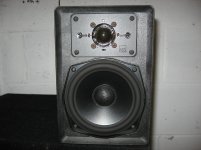
1. The photo of the bookshelf loudspeaker used as the load to the combo power amp driven with sine-wave test signals and music. The closed box resonance frequency of its woofer is 100 Hz.
2. The 47K feedback resistor shown in the schematic of the voltage source amp U1 is paralleled with 220K. This decreased its closed loop gain to a calculated 23.
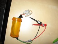
3. The photo of the tool I used to parallel the 47K feedback resistor with 220K is shown next to that of the loudspeaker. Note the clips.
4. The photo of the power amp's component side showing the 220K resistor attached with the tool's clips to the accessible leads of the 47K feedback resistor.
Here's are the process steps to move the experiment forward; reliably.
1. Open the switch at Vout of U1 voltage source amp
2. Minimize the resistance of the 25 Ohm potentiometer at Vin input of U1
3. Power up U1
4. Generate an adequate sine wave signal Vo at 100 Hz. Note its value.
5. Dial up Vin with the 25 Ohm potentiometer such that Vout of U1 is made numerically equal in value to Vo. I used a multi-meter on the AC scale to do so.
6. Close the switch so as to merge Vout with Vo across the loudspeaker.
7. Tweak the 25 Ohm pot to force the joined value of Vout/Vo to be equal to Vo before the switch was closed. This final action established the desired bootstrap status [with positive feedback] at 100 Hz.
8. This combo amp was stable against oscillation.
Subjectively, bootstrapping at 100 Hz boosted bass which was also tight as compared with the performance of the woofer with the switch off. The sonic difference [switch on versus off] was very clear.
I'll generate additional results of bootstrapping at 100 Hz, and 1 KHz, and report.
The attached schematic in the left view is that of the bench prototype which uses negative and positive feedback. Please note:
1. The photo of the bookshelf loudspeaker used as the load to the combo power amp driven with sine-wave test signals and music. The closed box resonance frequency of its woofer is 100 Hz.
2. The 47K feedback resistor shown in the schematic of the voltage source amp U1 is paralleled with 220K. This decreased its closed loop gain to a calculated 23.
3. The photo of the tool I used to parallel the 47K feedback resistor with 220K is shown next to that of the loudspeaker. Note the clips.
4. The photo of the power amp's component side showing the 220K resistor attached with the tool's clips to the accessible leads of the 47K feedback resistor.
Here's are the process steps to move the experiment forward; reliably.
1. Open the switch at Vout of U1 voltage source amp
2. Minimize the resistance of the 25 Ohm potentiometer at Vin input of U1
3. Power up U1
4. Generate an adequate sine wave signal Vo at 100 Hz. Note its value.
5. Dial up Vin with the 25 Ohm potentiometer such that Vout of U1 is made numerically equal in value to Vo. I used a multi-meter on the AC scale to do so.
6. Close the switch so as to merge Vout with Vo across the loudspeaker.
7. Tweak the 25 Ohm pot to force the joined value of Vout/Vo to be equal to Vo before the switch was closed. This final action established the desired bootstrap status [with positive feedback] at 100 Hz.
8. This combo amp was stable against oscillation.
Subjectively, bootstrapping at 100 Hz boosted bass which was also tight as compared with the performance of the woofer with the switch off. The sonic difference [switch on versus off] was very clear.
I'll generate additional results of bootstrapping at 100 Hz, and 1 KHz, and report.
Attachments
Last edited:
For the sake of simplicity, I defaulted to showing the attached original schematic of the Compound Amp wherein I did not in change the [parent] closed loop gain of U1 at 27. Please note the findings of these experiments:
1. With the switch OFF at Vout of U1, I did a frequency sweep [60 Hz to 1 KHz] across the loudspeaker by using the 2SJ28 amp. The result was the familiar Impedance versus Frequency plot of any woofer.
2. It follows that the 2SJ28 amp [call it U2] was operating [solo][ in the current source mode.
3. The relative woofer impedance at 200 Hz:100 Hz: 1000 Hz was 4 Ohms [quoted by ADS], to 20 Ohms at the woofer resonance of 100 Hz, and to 8 Ohms at 1 KHz.
4. The objective was, and still is to damp/en the woofer via U1 after its Vout switch is closed.
I then chose to bootstrap the woofer voltage at its closed box resonance of 100 Hz with a matching voltage from U1 by increasing the amplitude of its Vin.
1.It follows that [by definition of bootstrap] U1 did not dump current into U2 and the transformer #2 winding , and U2 did not dump current into the power output stage of U1.
2. It follows that no positive feedback was employed; because of this stalemate.
3. It also follows that the loudspeaker impedance as viewed by U1 is actually not 20 Ohms, but an integer multiple of 20 Ohms; say 50 Ohms because of this current bootstrapping phenomenon as published elsewhere by Nelson Pass.
4. Since the output impedance of U1 is for example a typical 0.1 Ohms, it follows that its Apparent Damping Factor was calculated as 50 Ohms divided by 0.1 Ohms or 500. Not shabby!
The bootstrap status at 100 Hz was kept; meaning Vin was untouched. The generator frequency was then increased to 1KHz.
1. Vo with the switch open was half the amplitude of the joined Vo-Vout [switch closed].
2. It follows that U1 and U2 now delivered equal power to the loudspeaker.
3. It also followed that positive feedback around U1 was enabled in this system.
Subjectively, impulse-type bass was tight with minimum overhang. The music was louder [yet clear and detailed] with the switch ON [joined Vo-Vout] versus OFF [Vo current source].
I'll follow up with a post on the findings due to bootstrapping at 1 KHz instead of 100 Hz.
Attachments
A detailed and [worthwhile] look at the combo amp
I repeated the experiments in post #190 by using one channel of Threshold S/150 instead of the Radio Shack power module. The left view is the schematic of the "combo amp" under test on the bench. The middle view gives graphical results which maybe understood as follows:
1. The vertical axis is for the output volts, Vout, Vo [in the schematic with switch open], and Vjoint with the switch closed; which merges Vout with Vo.
2. The horizontal axis is Log F which spans the test frequencies of 70 Hz to 1500 Hz.
3. At the outset, the magnitude of Vo [an independent variable] at 100 Hz was exactly shadowed by, or matched with an equal amplitude of Vout with the pot at Vin.
4. Vout tracks or is on top of Vo throughout the test frequency range.
5. Vjoint [after switch was closed] tracks [Vo and Vout] throughout the test frequency range; but also at a higher voltage level.
6. When Vjoint was say equal to 2 x Vo, the resultant power output was quadrupled which was observed [louder]; with the added benefit of the damping from S/150.
7. Tentatively, this combo amp is a low output impedance [from S/150] current source amp [from 2SJ28].
The far right view shows the evidence of positive feedback around S/150.
1. Vp is the voltage as shown in the schematic with the switch open.
2. Vp' is the voltage replacing Vp when the switch was closed.
3. S/150 energized the winding of transformer #2 [connected to load] because Vjoint was greater than Vo. This Vjoint was stepped up to become Vp' which was recycled back to the input of S/150; meaning +ve feedback.
Subjectively, this system was loud, detailed and generally sounded great overall.
The next post will report the performance of a combo amp due to S/150 shadowing the 2SJ28 current source amp at 440 Hz instead of 100 Hz.
Attachments
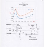
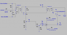
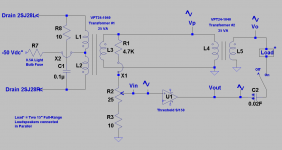
The following details the results of Threshold S/150 [R Ch], shadowing [at 440 Hz] the current source Analog Pulse amp which uses 2SJ28 VFETs in its power output stage.
1. The left view is the schematic of the "combo amp" under study. Its topology is the same as the ones shown in the 2 previous posts.
2. This schematic shows the variables Vo, Vout and Vp when the switch is OFF.
3. With the switch ON, the merging of Vo and Vout becomes Vjoint, and Vp becomes Vp'.
4. Firstly, with the switch OFF, Vout is made equal in magnitude to Vo [independent variable] at 440 Hz by adjusting the magnitude of Vin with the 25 Ohm pot at the input of S/150.
5. Secondly, the switch is closed, and now the resultant Vjoint is further tweaked [slightly] with the 25 Ohm pot at Vin of S/150 to ensure that its value is exactly equal to Vo when the switch was OFF.
6. The system was next ready for collecting data.
Data were next collected in the frequency range of 70-1500 Hz. A digital AC multimeter was used to measure voltage in that frequency range.
1. Firstly, open switch, apply a sine wave signal at 70 Hz of suitable amplitude.
2. Measure and tabulate Vo, Vout and Vp.
3. Close the switch, measure and tabulate Vjoint and Vp'.
4. Repeat the above three steps in the frequency range. It was done manually by advancing the frequency of the signal generator to 80, 90 etc...
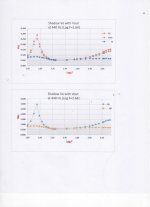
The right view shows 2 graphs of the data. They are the measured voltagee Vo, Vout, Vp, Vjoint and Vp' [Y axis] versus LOG F [X axis].
The top chart says the following:
1. With the switch OFF, Vout shadows Vo across the frequency range. Vo or Vout trace the impedance curve of the woofer. It follows that Vo emanates from a current source amp [in this case 2SJ28] which normally gives this signature graph.
2. With the switch ON, Vjoint [merge Vo with Vout] wipes out the signature impedance plot of a woofer, and is flat function in the frequency range. This combo amp is now exclusively a voltage source amp.
The bottom chart says the following:
1. With the switch OFF, Vp [see schematic], traces the classical impedance plot of a/the woofer, and essentially shadows Vo and Vout.
2. With the switch ON, Vp defaults or sinks to Vp' which is not representative of a woofer impedance plot.
3. Vp' shadows Vjoint of the upper graph. It follows because Vp' is lesser in value [e.g. in resonance region] of woofer or equal to Vp elsewhere, that there is not a path for positive feedback around S/150.
4. Since Vjoint defaulted to the value of Vo across the frequency range, S/150 is "bootstrapped" accordingly. It cannot dump power into the loudspeaker, and so the damping factor of the resultant voltage source combo amp is maybe higher that 80 [spec for S/150] as described in an earlier post.
This combo voltage source amp performed subjectively as the objective data said it should. It is clear [e.g test with Adele's Someone like You], highly detailed, and lifelike; but not as loud as the combo amp described in the previous post.
A lot of conclusions can be extracted from this study, and from previous others. Analog Pulse amplification works accurately; because of the high quality and broad scope of its resultant music.
1. The left view is the schematic of the "combo amp" under study. Its topology is the same as the ones shown in the 2 previous posts.
2. This schematic shows the variables Vo, Vout and Vp when the switch is OFF.
3. With the switch ON, the merging of Vo and Vout becomes Vjoint, and Vp becomes Vp'.
4. Firstly, with the switch OFF, Vout is made equal in magnitude to Vo [independent variable] at 440 Hz by adjusting the magnitude of Vin with the 25 Ohm pot at the input of S/150.
5. Secondly, the switch is closed, and now the resultant Vjoint is further tweaked [slightly] with the 25 Ohm pot at Vin of S/150 to ensure that its value is exactly equal to Vo when the switch was OFF.
6. The system was next ready for collecting data.
Data were next collected in the frequency range of 70-1500 Hz. A digital AC multimeter was used to measure voltage in that frequency range.
1. Firstly, open switch, apply a sine wave signal at 70 Hz of suitable amplitude.
2. Measure and tabulate Vo, Vout and Vp.
3. Close the switch, measure and tabulate Vjoint and Vp'.
4. Repeat the above three steps in the frequency range. It was done manually by advancing the frequency of the signal generator to 80, 90 etc...
The right view shows 2 graphs of the data. They are the measured voltagee Vo, Vout, Vp, Vjoint and Vp' [Y axis] versus LOG F [X axis].
The top chart says the following:
1. With the switch OFF, Vout shadows Vo across the frequency range. Vo or Vout trace the impedance curve of the woofer. It follows that Vo emanates from a current source amp [in this case 2SJ28] which normally gives this signature graph.
2. With the switch ON, Vjoint [merge Vo with Vout] wipes out the signature impedance plot of a woofer, and is flat function in the frequency range. This combo amp is now exclusively a voltage source amp.
The bottom chart says the following:
1. With the switch OFF, Vp [see schematic], traces the classical impedance plot of a/the woofer, and essentially shadows Vo and Vout.
2. With the switch ON, Vp defaults or sinks to Vp' which is not representative of a woofer impedance plot.
3. Vp' shadows Vjoint of the upper graph. It follows because Vp' is lesser in value [e.g. in resonance region] of woofer or equal to Vp elsewhere, that there is not a path for positive feedback around S/150.
4. Since Vjoint defaulted to the value of Vo across the frequency range, S/150 is "bootstrapped" accordingly. It cannot dump power into the loudspeaker, and so the damping factor of the resultant voltage source combo amp is maybe higher that 80 [spec for S/150] as described in an earlier post.
This combo voltage source amp performed subjectively as the objective data said it should. It is clear [e.g test with Adele's Someone like You], highly detailed, and lifelike; but not as loud as the combo amp described in the previous post.
A lot of conclusions can be extracted from this study, and from previous others. Analog Pulse amplification works accurately; because of the high quality and broad scope of its resultant music.
Attachments

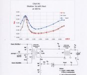
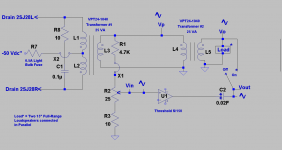
Here are results from using a full-range loudspeaker load to the combo amp instead of an enclosed two-way bookshelf loudspeaker[ADS L300C]. The middle view of post#81 shows the photo of this 15" full range driver under study. Two such drivers [8 Ohms each] were bolted to the ceiling, and were connected in parallel. The left view shows the schematic. I used a Threshold S/150 for U1 so as to generate reliable objective results , and to further experience the best subjective performance this system gives.
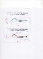
The protocol to collect data was given in the previous post. The charted data are shown in the right view. Please note the top chart:
1. The graph of Vo was generated with the switch OFF. It is the impedance curve of the equivalent loudspeaker. Above 100 Hz [Log F=2] impedance is ~4 Ohms. The peak impedance was ~12 Ohms at the woofers' 45 Hz resonance.
2. The switch was closed, and Vjoint was made equal in magnitude to Vo at 45 Hz by increasing Vin to S/150 with the 25 Ohm pot. The resulting frequency [Vjoint] tracked Vo in the frequency range of study. Vjoint was higher in amplitude that Vo on either side of 45Hz. This meant that S/150 was contributing power output to the load.
3. With the switch closed, Vin was increased such that Vjoint+ was 10% higher in amplitude than Vjoint. This gave the top graph which tracked [shape-wise] its two parents. Again, S/150 was asked to contribute more output power to the load; throughout the frequency range including at 45 Hz.
4. U1 in this instance is preferably an accurate amp like S/150 so as to get the best subjective performance which I did.
The bottom chart showed or implied that positive feedback was returned to Vin of S/150. The graphs of Vp'+>Vp'>Vp signal this feedback. Care needs to be exercised when Vin to S/150 is progressively increased; because the system will oscillate at some point.
I rated the subjective experience of this system [switch closed] an A+. The performance [legibility, and emotion] of female vocals was excellent; like Adele's [someone like you], Tina Turner's [what's love got to do with it], and Paula Abdul's [rush]. Some authoritative tight bass was also present, which was well-defined, and clear like the remainder of the audio spectrum.
Attachments
Mistake in schematics
I made a mistake in several similar schematics for the Load* power output section; via save as a file.... The schematics in posts #184 and 185 are correct. The schematics in posts 187 to 193 are not correct. The proper schematic is attached in this post. It needs to replace the faulty ones for the verbiage in their posts to make sense. I apologize for this error which may have led to confusion.
Here is the proper explanation. When the switch is closed at the power output of S150, Vout merges [meaning it makes electrical contact] with Vo to become Vjoint; which is the proper status.
Attachments
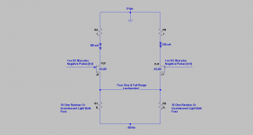
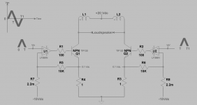
After a lot of meditation, I believe that the attached schematic is the best, simplest, and cheapest to implement a Class aP power amp. Its details are:
1. A model music signal is shown at the top left view. Note its voltage [Vac] at the zero crossing times of 0, T, and T1.
2. This model signal is precision rectified to give two independent analog pulses. The phase of the negative-going pulse from time T to T1 is then inverted.
3. The independent positive-going analog pulses are presented to the power output stage as shown in the schematic.
4. During the time [0 to T], the left TIP120 conducts above its idle bias current of 100 mA. The right TIP120 just idles at 100 mA as it has no input signal yet.
5. At time T, the right TIP120 begins to conduct above its idle current value while the left TIP120 goes back to idle.
6. The above describes Class B; but with an absent crossover [and its distortion] as this crossover was already done in the precision rectifier.
7. The TIP120s do not turn off.
8. The output circuit at the collectors of the TIP120s reassembles the model music signal.
9. The two coils [L1 and L2] can either be those of a dual voice coil [each 8 Ohms] woofer, or a choke [used a 100 VA power toroid]. The center tap of the coils goes to a +20 Vdc computer PSU.
10. Though it is normally contraindicated to pass direct current through a woofer or any driver, its suggested use here increases the system efficiency by adding acoustic output.
11. An enclosed loudspeaker is connected across the TIP120 collectors. It can be a full range, or multi-way.
This amp sounds great with any of the above output circuit combinations. I'll present an analysis of this amp [came to mind a few days ago] in a following post.
Attachments
Positive Current Feedback in Class aP power amp
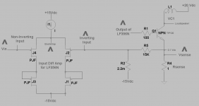
The attached schematic is for one half the Class aP amp I showed in the above post. I'll use it to explain Positive Current Feedback [PCF] in this amp; which I believe is straightforward to grasp.
1. The left side of the view shows the detailed schematic of the front end diff amp for LF356N operational amplifier.
2. The input analog pulse from the preceding precision rectifier [not shown] is presented to the non-inverting input of the LF356N diff amp.
3. This signal is processed inside LF356N and emerges at its output in phase with that of the input analog pulse.
4. The output analog pulse from LF356N then drives the base of TIP120 Darlington BJT.
5. TIP120 generates a current which flows through its emitter resistor [1 Ohm], and has the same magnitude as the current which flows through the loudspeaker load; meaning [Ie = Ic].
6. The analog pulse signal [Vsense] which is generated at the emitter of TIP120 and across the 1 Ohm sense resistor is next fed back to the inverting input of the front end diff amp of LF356N. It is in phase and has an equal magnitude as the signal presented to the non-inverting input of the front end diff amp.
PCF demands two conditions to be met:
1. A means to sense the current which flows through the loudspeaker load. This is Vsense across the 1 Ohm emitter resistor of TIP120.
2. The input analog pulse at the non-inverting input of the diff amp is bootstrapped by the fed back signal at the inverting input of the diff amp.
3 The depiction of 3 analog pulses at the input 2 PJFETs is a characteristic of any diff amp. They are in phase and equal in magnitude.
4. The extent of PCF [magnitude of the bootstrap voltage] is equal to the extent of overall negative feedback; inherent in the topology of this diff amp.
5. The value of the above is to minimize the operational internal resistance of TIP120.
So what? The perceived sound of an enclosed 2 or three way loudspeaker says that the loudspeaker was driven by a voltage source amp instead of a current source amp as clearly shown by its schematic [load at collector of TIP120]. That's one value of PCF.
Attachments
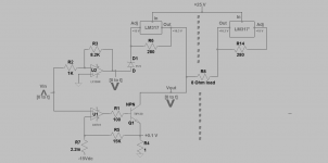
Dynamic load in Class aP amp
The following shows a 1/2 schematic of a Class aP power output stage which embodies a dynamic load comprised of LF356, and LM317. The vertical hashtags imply a virtual mirror which means there is a right side to this schematic which has identical components and identical idle conditions.
Lets examine the idle conditions:
1. The Output of LM317 is always 1.25 V higher in magnitude than that at the Adjust terminal
2. It follows that a current of ~4.5 mA flows through the 280 Ohm resistor, then through the 15 V Zener, and finally through the output of LF356 which is ~at 0 V and thus sinks this constant current to its -15 V negative power rail.
3. It follows that Vout of LM317 is at +16.3 V above common.
4. The 1/2 power output stage comprised of LM741 and TIP120 idles at 100 mA as was described in past posts. The collector of TIP120 is at +16.3 V, and LM317 absorbs its idle current
5. An 8 Ohm load joins the voltage outputs of LM317 which have equal values; meaning there is a minimal DC offset across the load. One needs to match the Zeners to achieve this.
Lets examine dynamic operation shown by Vin which is an analog pulse present during the real time spanning 0 to t.
1. LF356 inverts the phase of Vin and amplifies it by a factor of 8.
2. This gain of 8 is made equal to the numerical value of the minimum impedance of the loudspeaker. A must requirement.
3. Let Vin equal 1 Vpeak, and then let's describe the status of this output stage so as to understand its workings.
4. The following three simultaneous conditions exist.
4a. TIP120 is asked to pull 1 A peak through its 1 Ohm emitter resistor.
4b. The inverted output pulse of LF356 has a magnitude of -8 V peak; which then pulls the output of LM317 from +16.3 down by the same magnitude of this pulse towards ground. Thus, the peak voltage at the collector of TIP120 is now at 8.3 V.
4c. The 8 Ohm load resistor is sandwiched between two voltages. Namely a steady 16.3 V of the right side amp which is idle, and ~8 Vpeak at the collector of TIP120.
5. It follows [by Ohm's Law] that the 1 A pulse demanded by TIP120 now flows from +16.3 V through the 8 Ohms load then through TIP 120 and finally through its 1 Ohm emitter resistor to ground. Mission accomplished.
6. The above sequence repeats exactly with the other half of the amp when it receives the latter Vin' [time t to t1] signal.
Play this game. Let the above conditions be; but lower the value of the load to 4 Ohms from 8 Ohms. A problem or a violation of Ohm's Law arises. TIP120 can only deliver 1 A peak, but the 4 Ohms sandwiched across 8 Volts demands 2 A peaks; clearly a conflict; thus the must requirement above.
more to follow.
Attachments
Adapt Dynamic Load to make a Balanced Class A amp
The full schematic of the Class aP amp which I described in the previous post is attached. However I show it with minor modifications that extended its application to a concept Balanced Class A amp.
1. The LM317 chips limit power output. They can be bootstrapped for higher current delivery by using a published application.
2. The operation of the dynamic loads are exactly as I described them above for Class aP.
Back to the Class aP amp. It sounds great regarding clarity and broadband detail when I heard its performance using the enclosed 2, and 3-way ADS loudspeakers, and the unenclosed 15" full range by MCM.
Attachments
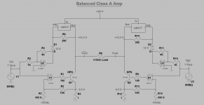
A good-news distraction from Class aP which shows another Class A amp
I apologize for an error in the schematic [balanced Class A] which I showed in the previous post. The load resistor should be 8 instead of 4 Ohms..
The dynamic load understudy is also useful in the following Class A amp that I depict in the attached schematic. I was surprised that it simulated very well by LTSpice. Its FFT showed a 0.04% THD which is solely H2.
For the sake of this concept Class A amp please make believe that LT1117 is equivalent to LM317. I needed it to run the LTspice simulation
Attachments
Last edited:
Hardwired the Precision Rectifier prototype
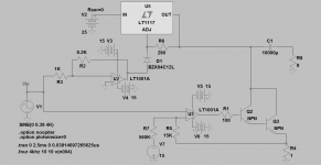
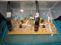
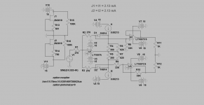
This is shown in the attached image. The circuit was assembled on a perf board, and enclosed in a Tuperware container which simplified drilling for the feed through of input, output and power lines. It shows a Right and a Left channels. The schematic which is attendant to each channel of the device is shown. Please note the following:
1. The first stage [rectifier] is LF356N instead of the LT opAmp which I used solely to run the simulation.
2. The output buffers are one dual OPA2134.
3. Chose switching diodes with the lowest forward voltage drop when passing 1 mA through. I chose 2 ~ matched diodes at 0.6 V.
4. Note the constant current sources [I1 and I2] using the 2N3819 JFETs to the left of the schematic. The resultant voltage drops of ~0.4 V across the 220 Ohm resistors forward biases the switching diodes for faster turn on.
5. The simulation runs smoothly as shown when using the attached asc file.
This precision rectifier may loosely be called an "analog source". It drove a power amp the output stage of which was configured as a Bridge Tied Load {BTL} which I'll elaborate on in a following post.
Attachments
- Home
- Amplifiers
- Pass Labs
- Class aP amplification