Morello said:
The cancellation is ofcourse not perfect, but single ended amps tend to produce much more distortion than a push-pull design.
Best regards\Morello")
Yes, that's pros and cons about the distortion .... but firstly we make DIY audio equipment is for enjoying music, not demonstrations of performance at the test bench.
vt4c said:dhengkoel,
May I know where did you obtain those 2SC1775 (E) ? Been trying to hunt some down.
Thanks,
C.K.
Try this: http://www.mouser.com/index.cfm?handler=displayproduct&&lstdispproductid=543676
or http://www.peacock.com.sg/stock/Hitachi.html
or http://www.candisc.com/ranger/stock1.htm
... or here in Indonesia
Regards:
ragil.hastomo
Hi Sdr Hastomo,
I should answer Christer first; yes, emitter degeneration is a good idea to some extent, however, the extent to which it reduces OLG must be controlled; we do not wish to throw away all our feedback factor as it is highly beneficial, applied correctly.
The best way I have found is to figure it empirically. That is, build the amp, then start inserting degeneration to test the sonic effect. I have found degeneration improves decay characteristics, particularly of voices in large spaces and hihats/cymbals. To much will start to overdo it but typically 10R-47R is best, depending on the nature of the voltage amplifier, of course.
Personally I like SE amplifiers, but I deplore their forced inefficiency, although Circlotron's approach using a choke as a load is a great idea, doubling efficiency. And in fact I would disagree that SE amps are necessarily highly distortive; if done with mosfets, the distortion is quite low and the sonic results are very close to utterly transparent.
I do enjoy the irony on this topic. Saying something but meaning quite the opposite is much under-rated, and there should be more of it, particularly in politics........ (perhaps then we could swallow the lies rather better?? . )
The feedback on dhengkoel's amp design is complex. It uses AC and DC feedback from the output stage to control offset and gain, and a further contribution from the voltage amp, together with compensation to pull the gain back at high frequencies to avoid instability. All connections are correct. This approach leads to a reduction of damping factor, leading to a softer, more musical bass and slightly less mechanical sound at midrange and high frequencies. However, measured performance (distortion and bandwidth) are usually not so impressive on paper.
Cheers,
Hugh
www.aksaonline.com
I should answer Christer first; yes, emitter degeneration is a good idea to some extent, however, the extent to which it reduces OLG must be controlled; we do not wish to throw away all our feedback factor as it is highly beneficial, applied correctly.
The best way I have found is to figure it empirically. That is, build the amp, then start inserting degeneration to test the sonic effect. I have found degeneration improves decay characteristics, particularly of voices in large spaces and hihats/cymbals. To much will start to overdo it but typically 10R-47R is best, depending on the nature of the voltage amplifier, of course.
Personally I like SE amplifiers, but I deplore their forced inefficiency, although Circlotron's approach using a choke as a load is a great idea, doubling efficiency. And in fact I would disagree that SE amps are necessarily highly distortive; if done with mosfets, the distortion is quite low and the sonic results are very close to utterly transparent.
I do enjoy the irony on this topic. Saying something but meaning quite the opposite is much under-rated, and there should be more of it, particularly in politics........ (perhaps then we could swallow the lies rather better?? .
)The feedback on dhengkoel's amp design is complex. It uses AC and DC feedback from the output stage to control offset and gain, and a further contribution from the voltage amp, together with compensation to pull the gain back at high frequencies to avoid instability. All connections are correct. This approach leads to a reduction of damping factor, leading to a softer, more musical bass and slightly less mechanical sound at midrange and high frequencies. However, measured performance (distortion and bandwidth) are usually not so impressive on paper.
Cheers,
Hugh
www.aksaonline.com

AKSA said:Hi Sdr Hastomo,
I should answer Christer first; yes, emitter degeneration is a good idea to some extent, however, the extent to which it reduces OLG must be controlled; we do not wish to throw away all our feedback factor as it is highly beneficial, applied correctly.
www.aksaonline.com
I think we must somehow have misunderstood each other. I
was referring to your claim that the collector load resistors
R4 and R25 are unnecessary. I did not talk about degeneration
resistors. Anyhow, as I said, it is probably not a big issue unless
we drop large voltages over the collector loads.
Ah, Scuza,
Christer, my mistake.
I never use a collector resistor on the feedback transistor of a diff pair. I ensure the bias feed to each base has equal resistance, match the two devices to within about 2%, and never have any trouble matching currents through the collectors, based on measurements of voltage drop across the base bias resistors.
Now, since you love the math, let's get to it.
Let's pass a milliamp of stage current; 500uA down each collector. Diff pair devices are PNP; voltage amp is fed from the collector load of the input device, which is NPN. Let's use 50V rails. Both diff pair emitters conjoined, and at maybe 0.7 volts above ground. The input transistor feeds a collector load of 1K5, and a base for the voltage amplifier, which runs at 630mV (these are actual measurements).
The two voltages across the base bias resistors are normally within 2% of each other, reflecting the tight match of the two devices. With a 47K input bias resistor and a good film cap (no leakage), I typically achieve 196mV on one transistor bias resistor, and maybe 199mV on the other. This demonstrates to me that the collector currents are equal. Of course, allowance should be made for the base current of the voltage amplifier, and this I normally allow for around 70uA. The base emitter resistor which constitutes the collector load of the input transistor is dimensioned to account for this; around 1K5 in my case.
Consider the Vce of both devices. One is 0.7 + (-50V), or -49V3, while the other is 0.7 + (-50 + 0.63) = -48.67.
The difference between these two Vce ratings is about 1.3%, worst case. If both are passing equal current (and the maximum deviation will be less than 2% anyway), then the dissipation of the input device is 24.35mW, and the feedback device, 24.65mW.
While there is clearly a minor imbalance (and I have detected far greater imbalances than this on the much-lauded current mirror topology commonly used in modern SS PP designs), I feel it is sonically insignificant, and I'd invite you to have a listen, and try to find precisely when this imbalance starts to affect the sound. At about 5-8%, in my experience..........
Now, let's go the step further and examine the current mirror topology. Let's assume we guarantee 500uA collector current on each leg, from a 1mA stage current as before.
However, this arrangement is bad news. If the voltage amplifier bias requirement is 70uA, a typical figure for a beta of 100 and a VAS stage current of 7mA, we need 70uA diverted to the base of the VA from the input transistor collector of the diff pair. This current flows from the collector of the input device, and thus 500uA exits, 70uA goes to the VA base, and the remainder, 430uA, passes through the current mirror. The other side of the current mirror, assuming moderately large degeneration, say 60mV minimum, will be duplicated; this gives 430uA on the feedback collector, an immediate imbalance and not even a total stage current of 1mA. In practice, the two collector currents will adjust to accommodate the allocated stage current of 1mA, and this leads to 535uA down the input device, and 465uA down the feedback device, but this further compounds the imbalance which, for these figures, stands at +/-7%. The only way around this problem is to use two very different degeneration resistors in the current mirror, and to exactly match the two transistors in the current mirror for Vbe.
Thus, I believe this demonstrates that diff pair balance is mismanaged by design to the tune of 7% with the ubiquitous current mirror, but with careful design, the resistively loaded diff pair can be brought easily within 2%. Of course, this will precipitate howls of protest, and I'm resigned to that, but interestingly, it is the math which demonstrates it.
I hope this properly responds to your point, Christer, and thank you for your perseverance. This was a long rant!
Cheers,
Hugh
www.aksaonline.com
Many good designs use a follower of some sort between the diff stage and VAS to minimize the effect of bias required by the VAS. Of course, one could say all kinds of bad things about followers
I guess this is more evidence of the judgement and compromise required for audio design.
Just to stir up trouble howzabout a Class A power amp based on this preamp design from Kevin Gilmore. Nice DC servo circuit. Also, you could easily use the side of the diff stage that is currently NOT driving anything to drive another output stage and make a balanced Class A amp. Any takers? Heh, heh
mlloyd1
I guess this is more evidence of the judgement and compromise required for audio design.
Just to stir up trouble
howzabout a Class A power amp based on this preamp design from Kevin Gilmore. Nice DC servo circuit. Also, you could easily use the side of the diff stage that is currently NOT driving anything to drive another output stage and make a balanced Class A amp. Any takers? Heh, hehmlloyd1
AKSA said:..... However, this arrangement is bad news. If the voltage amplifier bias requirement is 70uA, a typical figure for a beta of 100 and a VAS stage current of 7mA, we need 70uA diverted to the base of the VA .... The only way around this problem is to use two very different degeneration resistors in the current mirror, and to exactly match the two transistors in the current mirror for Vbe....
Hugh
What is the use of C20 and C14 ? Stability?
Without a collector resistor you can put the C's between the base of the transistors Q8/Q13 and the ground.
C20 and C14 limit the slew rate.
Would it be better to do the frequncy compensation using a C in each differential amplifier, between the collectors of Q2/Q3 and Q5/Q6 ? Or miller C's around Q1/Q7 ?
I'm just wondering.
Hugh,
you have shown that the power imbalance is minute and there not likely to cause a significant current imbalance which is what really counts. On the other hand, if there is some emitter degeneration in the VAS, its base will sit at 1 - 5 V. The power imbalance is still small, but adding the collector resistor in the feedback side of the diff pair has no real downside, doesn't it?
Thanks for pointing out that a current mirror should not be used with an unbuffered VAS stage. While D. Self stresses that the diff pair should be kept at <1% current balance and hence advocates current mirrors, he fails to make this point. This is probably because he likes the follower VAS best of all the configurations he discusses.
It should not be forgotten that the current mirror adds a factor of two in loop gain while not introducing any significant nonlinearity. So if the there is a buffer between diff and VAS stage, it might still be a good idea to use a curent mirror.
Back to the original schematic posted by dhengkoel:
Current matching is at the mercy of the matching of the NPN and PNP transistors used for the diff pairs and VAS stages (+ the symmetry of the supplies for the passive current sources used here, or at the symmetry of the current source LEDs and transistors if active sources were used). Any NPN/PNP imbalance creates an offset at the VAS output. Through the feedback loop, the diff pairs will compensate for this and bring the closed loop output voltage to zero, but they can only achieve this by moving away from their intially perfect current balance.
In my amp, I solved this by using expensive transistors and lots of selection. Having the DC servo act on one of the current sources rather than on the input of the diff pairs might be a way to move this burden away from the diff pairs.
Eric
a couple of quickies
1. Why not use a mosfet for the VAS stage thus incurring zero dc bias and leaving the currents balanced in the diff input stage?
2. I'm not sure what distortions people are measuring but a PP tends to sound much worse without a huge amount of care than any SE output I've heard. Much easier for most to get great sound from a SE output, albeit limited in volume.
Hi Eric,
I have an hour alone on a Saturday afternoon to spare (wife and kids enjoying retail therapy, there's always a price.......!) and so can set to and properly respond to your post. You write:
"You have shown that the power imbalance is minute and therefore not likely to cause a significant current imbalance which is what really counts. On the other hand, if there is some emitter degeneration in the VAS, its base will sit at 1 - 5 V."
I have found that most SS amplifiers have too much open loop gain, that is, too much feedback. This statement is based on my use of very fast, highly linear transistors, particularly in the emitter follower output stage. To me, the evidence of this came when when I began to refine my AKSA design by installing emitter degeneration on the diff input stage; a very small amount improved things, particularly decay on cymbals and other percussion. However, there are other factors.
On basis of the above, I figured that emitter degeneration of the voltage amplifier might actually be a retrograde step, and sure enough, it seemed that way. There was a mitigating factor, however. Emitter degeneration on the voltage amplifier -
1. Very considerably increases output impedance at the collector which in turn drives the output stage, making it more susceptible to the abrupt impedance changes at crossover. This is bad.
2. Elevates the operating point of the stage, increasing linearity. This is good.
3. Greatly increases the input impedance of the base of the VAS as seen by the collector of the input transistor. This means that as we invoke VAS emitter degeneration, and increase the value of the collector resistor of the input resistor, we hugely lessen the perceived load on the input transistor; changing the stage interface from essentially transconductance drive to ohmic drive. This is good, BUT, the cost is open loop gain, which precipitously drops.
4. Reduces the rail efficiency of the power amplifier since the negative half cycle cannot go so low; it does not approach the negative rail so closely. This gives premature negative clip, which many designers avoid like the plague.
5. Raises the value of the collector resistive collector load into which the diff pair must operate. On the face of it, this is good, since it improves gain, but in truth, this is a transconductance stage - voltage at the input transistor converted to current out at the base of the VAS, and here the rules change.
CONCLUSION:
The collector load on the input transistor of a conventional SS PP amplifier is essentially dominated by the characteristics of the VAS base/emitter junction it feeds, since any increase in voltage at the base is met with only tiny increases in base/emitter potential difference due to the abruptly dropping input impedance of the VAS as the transistor consumes more bias to conduct harder. This can certainly be ameliorated by use of emitter degeneration on the VAS, but only at the expense of OLG. As has been commented before, if we choose to eschew the current mirror as an active load for the diff pair, then we lose half our open loop gain immediately, and thus we probably need to compensate for this elsewhere. Furthermore, the input transistor collector resistor value importantly fixes the ratio of bias and drive current to idle current. This ratio is actually quite important to noise performance, and arguably sonics as well.
My careful tweaking here has revealed we need to run the voltage amplifier at full throttle, and fine tune the OLG of the circuit with a little degeneration on the diff pair. Of course, there is also the huge issue of stability, and generally, the higher the feedback factor, then the more difficult it is to achieve stability. There are many compromises here; I believe the big one is the nature of the load on the collector of the voltage amplifier, which should be arranged to load up the collector at the higher frequencies so we can meet the Bode-Nyquist criteria without hobbling the VAS at its collector/base. The lag compensation cap is a particularly noxious way of ensuring stability, since it has draconian impact on the sonics.
"The power imbalance is still small, but adding the collector resistor in the feedback side of the diff pair has no real downside, doesn't it?
"Thanks for pointing out that a current mirror should not be used with an unbuffered VAS stage. While D. Self stresses that the diff pair should be kept at <1% current balance and hence advocates current mirrors, he fails to make this point. This is probably because he likes the follower VAS best of all the configurations he discusses."
Yes, but look at the math. Let's say we run the VAS at 7mA, as before, and drive the base with a follower, a la Doug Self's suggestion. Since we have around 70uA of base current, and choose let's say 25 times this current (let's live extravagantly!!) to flow through the follower, this comes to 1.75mA of idle current. If the follower also has a beta of 100, then its bias current will be 17.5uA, say 20uA, which is still significant since we have change the bias/idle current ratio only by a factor of less than four. Further, the input impedance of the emitter follower is dominated once again by the base/emitter junction of the voltage amplifier, and we must ask ourselves if the supposed gain offsets the intrinsic non-linearities - and notably the phase errors - introduced by a further stage.
"It should not be forgotten that the current mirror adds a factor of two in loop gain while not introducing any significant nonlinearity. So if the there is a buffer between diff and VAS stage, it might still be a good idea to use a curent mirror."
You say there is no added non-linearity. This word is much misunderstood. Let's go further; does it sound any different? I say - from my tests over a long period and with many sets of talking ears - yes, it does. The current mirror drive does not sound the same as the resistive drive, and I prefer the latter by quite a margin.
Thank you for your thoughtful reply.
Sincerely,
Hugh
www.aksaonline.com
mlloyd1 said:[snip]
Just to stir up trouble
mlloyd1
I hate to burst the bubble, but this servo directly modulates the fet drain currents, and therefore the drain voltages that drive the driver stage. Since the amp has no way to know whether this modulation is an audio signal or the servo signal, it will happily put it on the output. This servo *is* in the audio loop
Sorry.
Jan Didden
Mike;
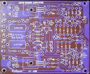
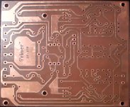
.. thank's for your attention .. i've learned your paper you send to me .. and I already change the schematic .. but the PCB is ready before I post the schematic here, and i'm not apply the short-circuit protection network on the PCB as your advice ..
regards:
Ragil Hastomo
.. thank's for your attention .. i've learned your paper you send to me
.. and I already change the schematic .. but the PCB is ready before I post the schematic here, and i'm not apply the short-circuit protection network on the PCB as your advice .. regards:
Ragil Hastomo
by kevin gilmore
2) Ultra high open loop gain REAL, REAL BAD!!!. That basically means anything with an op-amp in it. Op-amp circuits with open loop gains of 10,000 or more require large amounts of feedback to make them usable. While this reduces THD, the intermodulation products, and especialy the transient intermodulation products are much higher than they should be.
http://gilmore.chem.nwu.edu/head5.htm
This is ultra-wrong...

- Status
- This old topic is closed. If you want to reopen this topic, contact a moderator using the "Report Post" button.
- Home
- Amplifiers
- Solid State
- :: class a symetric power amplifier ::