revintage said:Hi Ikofl.....,
Now you got it! Sourcefollower with bypassed resistor or diode bias will keep Zout low.
To keep bias steady, circuit 2 in MJKs post could be used.
http://www.diyaudio.com/forums/showthread.php?postid=1815088#post1815088
Lars, what an excellent thread!
salas, I see now what you mean.
jeff, I will start simple so I have something to compare against, good idea.
Thank you all guys, I need to do some more reading.
Sheldon said:
Nah, more soldering.
Sheldon
Yes sir!
Seriously now, I think I got all the parts to start a prototype, so yes, next, hot iron.
Actually, after some more deliberation and thought (sorry to disappoint you Sheldon), this is my new plan. Gyrator+ccs plate load, direct coupling via p-channel mosfet, output transformer.
Fourier components of V(out)
DC component:1.97447e-008
Harmonic Normalized
Number Component
1: 1.000e+00
2: 8.115e-04
3: 6.001e-07
4: 6.098e-08
5: 2.473e-08
6: 2.456e-08
7: 2.170e-08
8: 1.967e-08
9: 1.676e-08
Total Harmonic Distortion: 0.081146%
Fourier components of V(out)
DC component:1.97447e-008
Harmonic Normalized
Number Component
1: 1.000e+00
2: 8.115e-04
3: 6.001e-07
4: 6.098e-08
5: 2.473e-08
6: 2.456e-08
7: 2.170e-08
8: 1.967e-08
9: 1.676e-08
Total Harmonic Distortion: 0.081146%
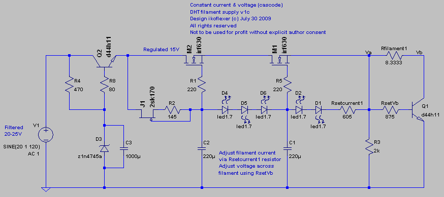
regulated PSU for dht headphone amp
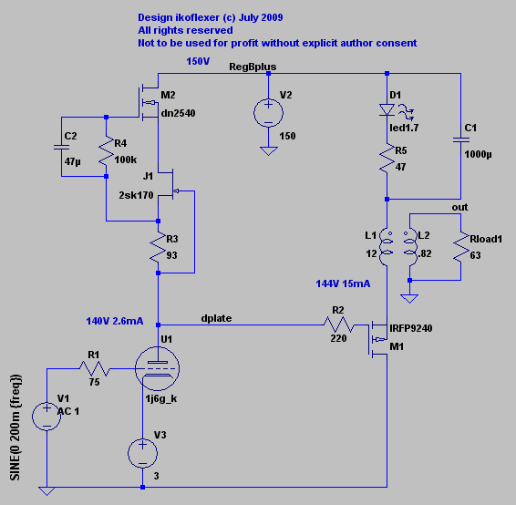
I've been thinking about the power supply for this amp and decided to go regulated via a shunt regulator.
This is what I have in mind.
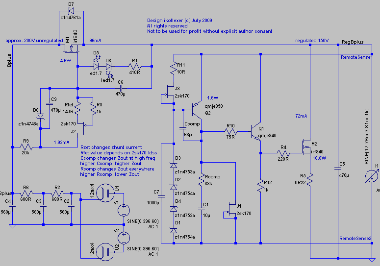
Output impedance can be even lower, and is settable via Rcomp. In reality it will depend a lot on the actual implementation.
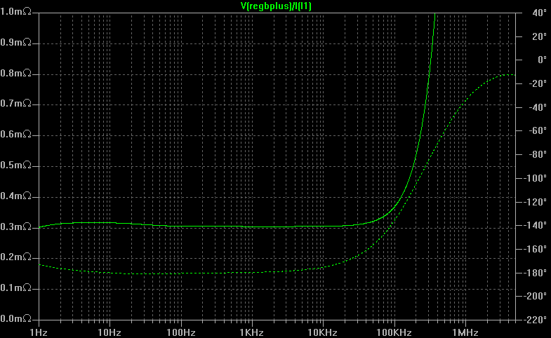
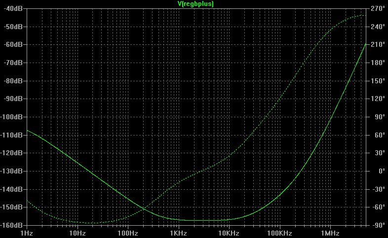
Capacitor C6 makes the input behave like a gyrator. Higher value, higher psrr. Here's the psrr plot with C6 in the circuit.
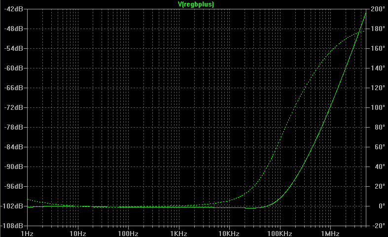
And without C6
Anything I should be worried about?
I also decided to not parallel the two halves of the 1j6g, this being the result.
The simulated distortion numbers are only an indication that the operating point choice is not too bad.
I've been thinking about the power supply for this amp and decided to go regulated via a shunt regulator.
This is what I have in mind.
Output impedance can be even lower, and is settable via Rcomp. In reality it will depend a lot on the actual implementation.
Capacitor C6 makes the input behave like a gyrator. Higher value, higher psrr. Here's the psrr plot with C6 in the circuit.
And without C6
Anything I should be worried about?
I also decided to not parallel the two halves of the 1j6g, this being the result.
The simulated distortion numbers are only an indication that the operating point choice is not too bad.
Code:
Fourier components of V(out)
DC component:5.00563e-007

Harmonic    Frequency    Fourier    Normalized   Phase      Normalized
 Number       [Hz]      Component    Component  [degree]    Phase [deg]
    1       1.000e+03   9.177e-01   1.000e+00      -2.18°       0.00°
    2       2.000e+03   8.179e-06   8.912e-06    -150.55°    -148.37°
    3       3.000e+03   3.900e-07   4.250e-07      16.21°      18.40°
    4       4.000e+03   1.921e-08   2.094e-08      87.11°      89.30°
    5       5.000e+03   1.339e-09   1.459e-09    -176.10°    -173.92°
    6       6.000e+03   1.387e-10   1.512e-10     -89.26°     -87.08°
    7       7.000e+03   6.713e-11   7.315e-11     -41.33°     -39.14°
    8       8.000e+03   8.919e-11   9.718e-11     -24.67°     -22.49°
    9       9.000e+03   1.188e-10   1.295e-10     -14.81°     -12.63°
Total Harmonic Distortion: 0.000892%


Fourier components of V(dplate)
DC component:140.513

Harmonic    Frequency    Fourier    Normalized   Phase      Normalized
 Number       [Hz]      Component    Component  [degree]    Phase [deg]
    1       1.000e+03   3.993e+00   1.000e+00     179.38°       0.00°
    2       2.000e+03   2.701e-05   6.765e-06      -8.41°    -187.79°
    3       3.000e+03   8.321e-07   2.084e-07     -97.22°    -276.61°
    4       4.000e+03   2.135e-08   5.348e-09     -16.54°    -195.92°
    5       5.000e+03   2.275e-09   5.699e-10      85.41°     -93.98°
    6       6.000e+03   7.664e-10   1.920e-10     170.54°      -8.84°
    7       7.000e+03   6.976e-10   1.747e-10     176.50°      -2.88°
    8       8.000e+03   7.893e-10   1.977e-10     176.56°      -2.82°
    9       9.000e+03   8.882e-10   2.225e-10     177.48°      -1.90°
Total Harmonic Distortion: 0.000677%Thanks salas. I'm not sure what you mean by the relaxed capacitive loading region. But I wasn't very careful about the cap values. Most likely I'll be using 10uF 680R 10uF 680R 68uF, which results in ripple of about 300mV, well within the regulator ability to smooth things out.
The promising thing about this regulator is that the performance is very adjustable. I'm pretty sure it can be made stable, and am planning to build that first. It's the usual recipe, gyrator (or ccs) feeding the shunt. I added a few parts for biasing and over voltage protection. Even though it may look more complicated, it's quite simple. I opted to discard the usual cascode that I was using before, because there is no need for it in this one. Not shown, but I've run a lot of tests on it to try and break it, as I usually do. The remote sensing labeling is there just for completion, I don't plan to do it.
This whole thing probably defeats the purpose of using tubes. I mean, one lonely tube in the middle of a forest of solid state beasts
The loading current of the 560u is pretty large and I'm sure it would pretty much toast the 12ax4 Good catch. I think I'll update the schematic.
Edit: actually I'll pay some more attention to the rectifier+filter part of the schematic, because it was pretty much neglected so far. I may have no choice but to use ss diodes.
Good catch. I think I'll update the schematic.Edit: actually I'll pay some more attention to the rectifier+filter part of the schematic, because it was pretty much neglected so far. I may have no choice but to use ss diodes.
Slow progress here. Finished the HV shunt regulator, a bit simpler than the schematic shown, but it works.
Now I'm not sure about the filament supply. Here's something I have in mind. I'd like to keep it simple. The current is set to 240mA, but can be adjusted. Also, the voltage at Va is 2.6V, which is the operating point I'd like to use with this tube. Voltage drop across the filament is about 2V, also adjustable.
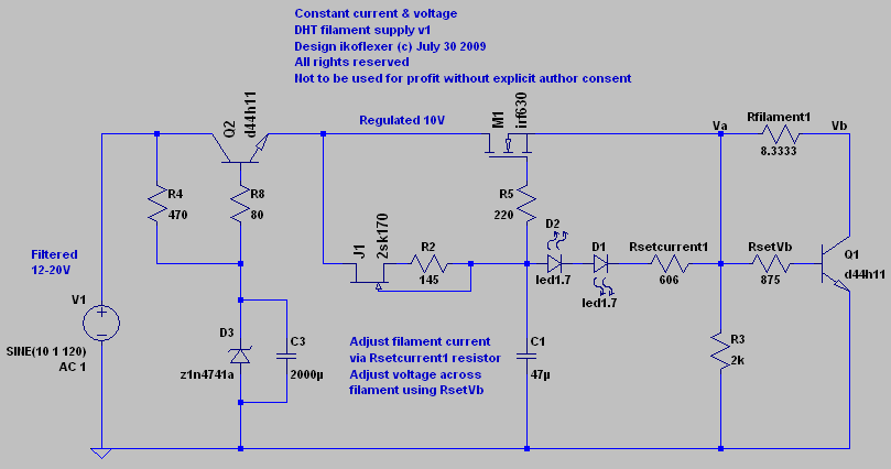
Now I'm not sure about the filament supply. Here's something I have in mind. I'd like to keep it simple. The current is set to 240mA, but can be adjusted. Also, the voltage at Va is 2.6V, which is the operating point I'd like to use with this tube. Voltage drop across the filament is about 2V, also adjustable.
No I chickened out, I'm building a 6c45pi/5842 spud SEOPT amp with Salas HC Shunt instead. Maybe one day I'll try a 71A with the circuit as I don't need much gain for my headphones (Grados.) I think DHT SE head-amps are a DIY area worth exploring (especially for Grados which are very challenging with their high sensitivity.)
Have you built and tested the DHT filament supply circuit shown in post#71?
I have, but I haven't worked on this project for a long time. Better options exist now:
http://www.diyaudio.com/forums/tubes-valves/151421-26-pre-amp-28.html#post2016042
and
http://www.diyaudio.com/forums/powe...-voltage-shunt-regulator-162.html#post2014178
Hello All,
I saw DHT headphone amplifier and had to look in. After searching for 300-ohm output transformers I spoke with the people at EDCOR. EDCOR made for me what they call GXE3-300-5K transformers. This is a 3 watt output 5K to 300 ohm headphone output transformer with a UL tap on the primary. Cheap at $20.00 US each. I am using 6BQ6GTB’s. I listen to this breadboard headphone amplifier every day, I am happy with it. I am going to keep it running while I play with 307A DHT's.
DT
All just for fun!
I'm resurrecting this old thread about the dht headphone amp which I put aside for a long time. Meanwhile I got another idea and am looking for comments.
I'm haven't decided exactly the specs, but roughly these features are what I was aiming for:
* simple to build and get working
* use a direct heated tube in the first stage
* use parts which are fairly easy to obtain and cheap
* low voltage power supply, the simpler, the better
* decent performance, with low high order harmonic distortion
* no high value capacitors in the signal path
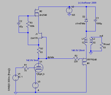
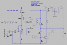
The circuit is shown below in the first image and is very simple.
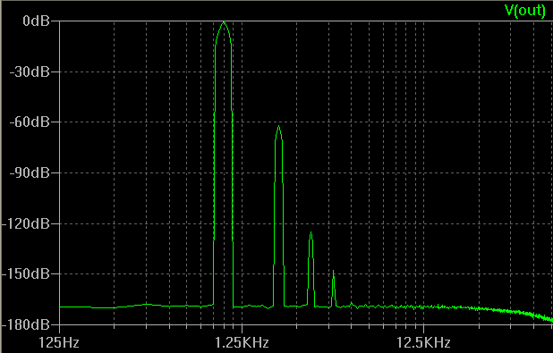
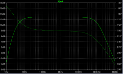
The second image shows the frequency response. I used compensation capacitors to avoid oscillations.
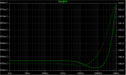
The third image shows the output impedance. This amp should be able to drive even lower impedance headphones, say 32 ohms.
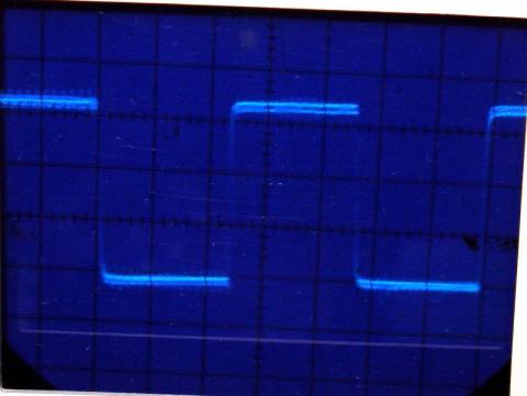
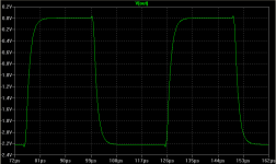
The fourth image shows the amp response to a square wave with 1uS rise and drop, and 100uS period. This simulated image looks almost exactly as the oscilloscope image for a similar square wave.
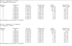
The fifth and sixth images shows distortion numbers for 1kHz and 5kHz respectively. It's not stellar, but it's not very bad either.
So I've built this circuit using IRFBC40 mosfets at the output, and R4 = 2R2. So the idle current is somewhere around 330mA, and the mosfets are hot. The rest of the values almost exactly as shown. In the prototype I left out the servo. It seems to be stable and working, but I haven't run any distortion tests on it.
The thing is, I don't have much experience with this kind of thing and any advice is appreciated. There are probably some blatant mistakes I've done.
I'm haven't decided exactly the specs, but roughly these features are what I was aiming for:
* simple to build and get working
* use a direct heated tube in the first stage
* use parts which are fairly easy to obtain and cheap
* low voltage power supply, the simpler, the better
* decent performance, with low high order harmonic distortion
* no high value capacitors in the signal path
The circuit is shown below in the first image and is very simple.
The second image shows the frequency response. I used compensation capacitors to avoid oscillations.
The third image shows the output impedance. This amp should be able to drive even lower impedance headphones, say 32 ohms.
The fourth image shows the amp response to a square wave with 1uS rise and drop, and 100uS period. This simulated image looks almost exactly as the oscilloscope image for a similar square wave.
The fifth and sixth images shows distortion numbers for 1kHz and 5kHz respectively. It's not stellar, but it's not very bad either.
So I've built this circuit using IRFBC40 mosfets at the output, and R4 = 2R2. So the idle current is somewhere around 330mA, and the mosfets are hot. The rest of the values almost exactly as shown. In the prototype I left out the servo. It seems to be stable and working, but I haven't run any distortion tests on it.
The thing is, I don't have much experience with this kind of thing and any advice is appreciated. There are probably some blatant mistakes I've done.
Attachments

There seems to be a problem. As soon as I connect the servo to the jfet gate the amp starts oscillating wildly. Without the servo it works fine.
You forgot a resistor in the servo integrator loop.. You were aiming for a two pole integrator. Add a resistor between C5 and the summing node of your op-amp, something like 100K ought to be fine.
Edit: What do you mean by 1m capacitor? 1000uF? - if so these should probably be more like 1uF unless you like time constants of hours..
Last edited:
- Status
- This old topic is closed. If you want to reopen this topic, contact a moderator using the "Report Post" button.
- Home
- Amplifiers
- Headphone Systems
- Class A, DHT driven, headphone amp