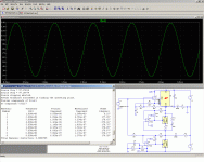
Are +/-12,15,24v fixed regulators can also be used here or are they possible to use?
In principle, you could use any ordinary voltage regulator (78xx) for the top and and bottom ones.
The middle one serves as a CCS, and using even a 7805 will reduce substantially the headroom, so it's best to leave a 317 there.
Anyway, the 317's and 337's generally have better performances than fixed voltage ones, and using other types could only be justified to increase the maximum output current.
I have a bunch of fixed regulators from 5v to 24 v.....can you show me how to put this to work as what you said above...the center i will leave it as adjustable since i have few LM317 and a single LM337. I will just try to build it.. BTW how many watts of Class A music power is in these intriguing circuit here...Thanks
For the top and bottom regulators, it's just a drop-in replacement: you have nothing to change, the opamp takes care of the different voltages.I have a bunch of fixed regulators from 5v to 24 v.....can you show me how to put this to work as what you said above...the center i will leave it as adjustable since i have few LM317 and a single LM337. I will just try to build it.. BTW how many watts of Class A music power is in these intriguing circuit here...Thanks
Here is an example with the top regulator replaced by a 7805: it works exactly the same, the performances aren't even affected (that's in the sim of course).
You must not go to high in the voltages, otherwise you will encounter headroom issues. But 5, 6, 8, 9 or 10V should be fine, both for the positive and negative ones.
Note that I didn't make any physical tests with those modifications, and in the real world, compensations might need some tweaking.
The 7805 model comes from the Yahoo group:
http://tech.groups.yahoo.com/group/LTspice/files/ Lib/Linear Regulators/
The output power with this version is determined by the peak current of the regulators, in principle 1.5A.
On a 8R load, this translate into 9W average power, provided the supply voltage is sufficient: a minimum of +/-24V would be required, and that would be too much for the opamps.
It would be possible to feed the top opamp in +24/-8, and the bottom one in +8/-24.
You could also use higher voltage ones, like the NE5532 f.e., this would also increase the performances.
Also note that voltage regulators pass in fact a significantly higher current than 1.5A: some go over 3A when they are properly cooled.
But to benefit from the higher current, you need to adapt the middle active current source/sink.
Attachments
It would be possible to feed the top opamp in +24/-8, and the bottom one in +8/-24.
Pardon please I'm a little bit confused, you mean unbalance supplies for the upper and lower opamp instead of usual +/-18v and not lower than +/-8v? I'mplanning to use LF353 opamp which i have.
Also, there are already two outputs(2 channel but 1 input) so this is bridge mode. can a single 8 ohm load or 2 x 4 ohms will be okay?
thanks
Yes, but that's pure speculation in case you want to increase the output power to the max.Pardon please I'm a little bit confused, you mean unbalance supplies for the upper and lower opamp instead of usual +/-18v and not lower than +/-8v? I'mplanning to use LF353 opamp which i have.
I don't recommend you do that, at least for now.
You already intent to depart from the original project by using 78xx's, which hasn't been physically tested, if you add further untested modifications you embark on a completely new and untested project.
Begin by building this one exactly as it is, and when it works and you're confident enough, you can begin to tweak.
I have given the usable schematic here:Also, there are already two outputs(2 channel but 1 input) so this is bridge mode. can a single 8 ohm load or 2 x 4 ohms will be okay?
http://www.diyaudio.com/forums/chip...mp-now-complementary-version.html#post2650551
Note that your spare 1/2 LF353 can be used to buffer the lower channel (L), that's what I did on my prototype. Just wire the 353 in unity gain follower.
Last edited:
- Status
- This old topic is closed. If you want to reopen this topic, contact a moderator using the "Report Post" button.
- Home
- Amplifiers
- Chip Amps
- Class A Chip Amp: and now, the complementary version
