When I was working on the one here, I blew so many output devices trying to get the opamp to work that I had no real interest in pushing it by testing into a 4 ohm load. It did crank out a hair over 200W into 8 ohms, so it's certainly underrated at '150W into 8 ohms' as HK says.
It would only be a guess, but I'd think that 240W probably wouldn't be too unrealistic.
Ship it here and I'll test it for ya.")
It would only be a guess, but I'd think that 240W probably wouldn't be too unrealistic.
Ship it here and I'll test it for ya.
Well, perhaps I'll get my scope on it and measure the output at the point where foldback kicks in. I'll put 4ohms of resistance on it and calculate the power from that.
I calculated the foldback might be near 8 amps, is that correct? (Or does anyone even know?)
8 amps into a 4 ohm resistive load is about 256W so perhaps 240 is a very close number. Being 32V, I can imagine the amp might easily swing near there.
Who knows.. Either way, a test is in order to find out.
I'd imagine that if all the outputs were replaced with a much larger motorola (onsemi) type that one could raise the current limit to a much higher current and have the amplifier deliver a lot more power to low impedance loads. Would the transformers handle this sort of loading? Perhaps if I increased the max output to about 10A which would yield 400W?
Maybe that's a little insane.... my ideas lol
Hmm, I'm guessing that the most effective way to pull the foldback off a bit would be to introduce a B-E resistance on the two foldback limiting transistors so that with the 360 ohm base resistor, I'd have a divider, whose inpututput ratio should be quite easy to calculate.
EDIT, ack, the emoticon engine didn't like that syntax.
utput ratio should be quite easy to calculate.EDIT, ack, the emoticon engine didn't like that syntax.
Duo said:Well, perhaps I'll get my scope on it and measure the output at the point where foldback kicks in. I'll put 4ohms of resistance on it and calculate the power from that.
I calculated the foldback might be near 8 amps, is that correct? (Or does anyone even know?)
8 amps into a 4 ohm resistive load is about 256W so perhaps 240 is a very close number. Being 32V, I can imagine the amp might easily swing near there.
Who knows.. Either way, a test is in order to find out.
I'd imagine that if all the outputs were replaced with a much larger motorola (onsemi) type that one could raise the current limit to a much higher current and have the amplifier deliver a lot more power to low impedance loads. Would the transformers handle this sort of loading? Perhaps if I increased the max output to about 10A which would yield 400W?
Maybe that's a little insane.... my ideas lol
did you messure Citation Sixteen in 4 ohm ?
From the manual:
"Transistors Q3, Q4, Q7, Q8 are used in the current foldback scheme. The circuit is designed to that the amplifier will deliver the 11.1 peak ampere current required for a 250 Watt output at 4 ohm load, but ... zero ohms the current is limited to approximately 8 amperes."
/edit:
The adjustments should be done cold and at 15 minutes powered on with no load or signal.
+/- 10mV output offset from the amp
"about" 10mV across one of the 0R5 resistors.
old tread
I have an old sitation sixteen now.
I only cant find the ic your talking aboud on the driver board. My serial on the driverboard is 00133497(assy)
At powering up and shutting off my speakers move in and out slowly .( maybe the relay doesnt work ?? )
One channel has a 200 mv offset the 1 M ohm pot seems ok
anny aditional info on this type off driverboard ?
Attachments
You either have a Citation 16 II, or the driver board from a 16 II, which uses discrete circuitry instead of the opamp.
All the schematics show a relay, but I've never actually seen a Citation 16 that had the relay (admittedly, I've only seen three of 'em). Perhaps your amp also does not have a relay.
All the schematics show a relay, but I've never actually seen a Citation 16 that had the relay (admittedly, I've only seen three of 'em). Perhaps your amp also does not have a relay.
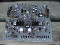
rofl, discrete circuitry???? lol, then what's that little metal can (AKA op amp) in the board at the input??
It appears that they elected to use a different style of package for their opamp in this design, and the transistors are sinked, (mine are not.)
I'm in the process of modifying my boards to be entirely descrete though, which might be a nice improvement since I could remove a lot of the RF filtering around it.
Anyway, definitely that little can with eight pins would be your opamp in this board. It probably works in exactly the same was as mine.
(CORRECTION) It seems I was having a bit too much fun eating my foot there. At a second look at the picture, I realize that the can is simply a dual transistor. Which would make the amp discrete.
Sorry for the confused mess. lol
the can is a 2N2916
45V Vce, 0.03A Ic, 60MHz NPN bipolar transistor
The chematics of the citation sixteen in this tread dont even look like mine .
It realy sounds nice this vintage baby .Metal sounds and other extream complex soundscapes are more open compared to my denon poa amps .Iam sure its nothing special compared to new first class amps but somehow i love the sixteen .
the dc offset of one channel is 200 mv 1 M ohm o pot . Maybe put in a 2 Mohm pot ? my guess is that somthing isnt ok around the 0 pot . pfff I feel live a rooky
I want xlr inputs on this sixteen . Where shoud i connect the ground from the xlr ? same place as the ground from the power input ?
I also want to exchange the speaker binding posts . But I guess i nead to desolder alot of wirers to get near them . I was hoping the casing could fold open ( rear plate ) . But all the short wirers dont let me
sorry for bad englisch
Well, for one, this amplifier could easily be adapted for balanced input, which is something I also intend to change on mine.
As with speaker binding posts, yes, they are a bit of a task to get out.
That 200mV offset is not a nice thing though. I would check the pot in that area to see what's going on. Perhaps a part value has drifted or maybe something is disconnected because of a bad solder joint or other simple problem.
The ground for the XLR would be the same as the ground for the SE inputs that it already has. This ground is found on the board and ends up connecting to the main ground of the amplifier.
I have a old song here whit a offset . When i change volume you can see my speakers go in or out to correct the offset giffen by the input .. hmm
Maybe it also has to do sompting whit my error . The feedback loop isnt seen by the driver pcb
or is the feedback loop somthing completly diverend compared to the zerro 1 M ohm pot ?
further upgrades . Any caps in the audio path that can give some improvements ?
Maybe it also has to do sompting whit my error . The feedback loop isnt seen by the driver pcb
or is the feedback loop somthing completly diverend compared to the zerro 1 M ohm pot ?
further upgrades . Any caps in the audio path that can give some improvements ?
the 200 milivolt offset is always there .
speaker or amp doesnt get warm from it . The offset pushes the speaker 1 mm out al the time .. so that one has a smaller X-max
First iam goint to check all connections and put in some new xlr,s and speaker binding posts. then ill try again
speaker or amp doesnt get warm from it . The offset pushes the speaker 1 mm out al the time .. so that one has a smaller X-max
First iam goint to check all connections and put in some new xlr,s and speaker binding posts. then ill try again
Hi mischa,
I agree with djk. Don't change those things out until you solve this other problem. The feedback cap going leaky would do this, as would a bad diff. pair. I still think you need to check the input coupling caps. One really sounds like it's leaky. If you disconnect them and the offset drops you have found your problem.
-Chris
- Status
- This old topic is closed. If you want to reopen this topic, contact a moderator using the "Report Post" button.
- Home
- Amplifiers
- Solid State
- Citation Sixteen