I am looking for the very first RCA papers/manuals/application notes from that time, where reportet about the 2N3055. Perhaps you know the exactly title and the date of release. About
http://www.diyaudio.com/forums/parts/167680-vintage-transistors-4.html
(go to post #33 and #34) I have posted some cover pics from old RCA books - perhaps one of this book is that, what I need.
Additional I want to have pics or URLs about the very first advertisement of the 2N3055 (about wikipedia I read, the date of release was in the early 60's, but I don't find the exactly date).
Perhaps you know this - thanks for advices.
Hi, sorry I just noticed this post.
I don't really know the history that well. I have in front of me here the 1969
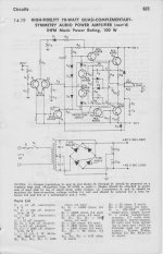
RCA "Transistor Thyristor & Diode Manual" from the technical Series SC-14.
It has a 70W reference design that is *very* similar to the HK Citation 12.
HK substituted most of the transistors and increased several of the caps in
the signal path to lower the LF cutoff. Both used output transistors in the
2N3055 family in that they were of single diffused planar construction as it
was called but neither used 2N3055 outputs - the RCA design used 40411,
and the HK used 40636 types.
I remember that our previous RCA Transistor Manual had amplifier reference
designs based on Germanium transistor but I am not sure of the year, probably
somewhere between 1966 and 1968.
I don't ever remember advertisements for the 2N3055 but I'd guess that it came
out a good number of years prior to the 1969 app note. I was too young to have
been reading any of the trade journals.
Perhaps you could get a copy of this:
http://ieeexplore.ieee.org/xpl/freeabs_all.jsp?arnumber=960371
and: http://www.ck722museum.com/history/rca/OralHistory/Meisel/Meisel_Page3.htm
Last edited:
More history: First production TO3 package Silicon power transistor?
http://www.pbs.org/transistor/science/events/silicont1.html
The RCA transistor manual that I have:
http://www.trademe.co.nz/Books/Textbooks/Other/auction-328327775.htm
http://www.pbs.org/transistor/science/events/silicont1.html
The RCA transistor manual that I have:
http://www.trademe.co.nz/Books/Textbooks/Other/auction-328327775.htm
Last edited:
Mr Pete Basel
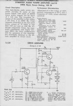
Would you be able to e-mail me a copy of the schematic and component list for the 70W reference design from your 1969 RCA Transistor Thyristor & Diode Manual?
My e-mail address is "agedone_2004@yahoo.com"
I have been trying to get this schematic for a long time without success; thank you for any assistance you may be able to give
Mr Basel
Got it.....Thank you again
You're welcome and please call me Pete no need for the Mr.
Hello everyone.
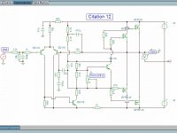
I don't think I should start new topic, so I'll just ask here. I am having IRFP9140's and IRFP240's. I have read that this is better pair than IRFP240 and IRFP9240. Look at schematic please, and correct me if I have redrawn it wrong. At simulation it runs well, only negative swing clips at lower level than positive does.
Ah, imagine source resistors in your mind
Attachments
Last edited:
On-Semi models
A bit late in reply but Bob Cordell has been using these 243/253 types in his smaller triple EF designs to keep a lid on the overall O/P stage Hfe. We could assume the LT spice models on his website are correct, since he's had to find out the hard way too.I'm getting solid results now, the solution was to avoid the MJE243/253s and use the MJE15034/35 instead. I believe that it's a model problem with the MJE243/253 but I cannot be sure without measuring the parts or checking for an obvious problem in the model.
Hi Ian,
You mention late, yes the post you quoted was in 2005, I do have the sim around here somewhere and I could use Bob's models. I still need a realistic model for the output devices. Bob shows very high distortion in his book for the simple topologies but it is due to slew rate limiting - I pointed this out and used the Citation 12 as an example that does not slew rate limit at full power and 20 KHz. I'll probably revive the simulation, get the models sorted out in order to prove my point. It is not really necessary since both the published distortion and that verified in test reports show low distortion at 20 KHz full power for the Citation 12.
You mention late, yes the post you quoted was in 2005, I do have the sim around here somewhere and I could use Bob's models. I still need a realistic model for the output devices. Bob shows very high distortion in his book for the simple topologies but it is due to slew rate limiting - I pointed this out and used the Citation 12 as an example that does not slew rate limit at full power and 20 KHz. I'll probably revive the simulation, get the models sorted out in order to prove my point. It is not really necessary since both the published distortion and that verified in test reports show low distortion at 20 KHz full power for the Citation 12.
Hi
In response to post #21 - has anyone got an RCA advert from ~1964-1965?
The 2N3055 was advertised along with the 2N3054 and 2N3053 originally as a range of NPN power transistors. The ad ran for a few weeks in the electronics press.
Regarding transistor subs - the 40636 seems to be a 95V (Vcer) selected 2N3055, the 2N3055 can be used as a 40363 directly. The 40411 seems to be a type of transistor from the 2N3772 family, with 800kHz typical ft -but a poor 200 kHz min, probably, but that is not given in the data sheets.
I've indicated before that the latest (epi) 2N3055 transistors from e.g. ON semi or ST are very likely to be able to be used at over 80V and maybe up to 100V, but you should check, you cannot take this for granted. THe reason is that epi transistors don't appear to have the same Vcbo:Vceo differences that the original diffused 2N3055 had and the manufacturers MAY have to build a 100V Vceo epi transistor just to ensure that Vcbo is met, but they won't change the data sheet which says 60V Vceo.
I've certainly had off-the shelf ST and ON semi parts which work to over 80V Vceo and can be used in at least a 60W amp and MAY give 70W.
BD139-Bd140 can be used instead of 40409/40410. I'd recommend MJ15003/4 for a fully comp pair for 70W and if you need higher voltage drivers you should try the 2SC4793/2SA1837 which are high speed but can dissipate almost 10W at 100V, while the BD139/BD140 are working in the Vcer range at 100V, but this is how RCA specified their drivers. To use a BD139 as a VAS with 90V rail to rail probably needs to have at least a low impedance base resistor and probably a small emitter resistor to assist.
John
- Status
- This old topic is closed. If you want to reopen this topic, contact a moderator using the "Report Post" button.
- Home
- Amplifiers
- Solid State
- Citation 12 Substitute Transistors