actually I never listened attentively to tubes amp, but to talk about this amp, it's for sure a very interesting one, even compared to high end amps , according to your speakers behavior some amps can sound better than some others, but this one has the advantage of working wether AB (rather inexpensive)or A (add some bucks for the heatsinks), and sounds great wether what class you choose, and an important thing is that ias long as you take care of wires lengh and soldering job it doesn't keep oscillating ...
actually for me and IMHO a very good project ,easy and effiscient, you can go ahead!
Vince
actually for me and IMHO a very good project ,easy and effiscient, you can go ahead!
Vince
I think I might after I finish my next tube amp.
Tube amps and Solid state amps get along in reality, the truth is that the crappy OP-amps of today sound like total crap compared to tubes, and the MOSFET is the transistor of choice for the Tube lover, its supposed to have a really good (pentode) tube sound with better bass, this project looks really cool, as I love anything HK
does anyone sell PCBS for this amp?
Actually what can surprise in this amp is that althought it's very dynamic (especially on my horn med drivers) it never irritate ears even on big peaks, med and highs are really sweet compared to all the bipolar amps I have here it really has unique sound very enjoyable, and again impressive power impression, actually you'd bet you have a 200w power amp althought it'just 40w approx considering my low rails voltage...
of course exactly like in good amps the sound is good wether played lo or high , even played very loud it doesn't loose any of his qualities.
I used 160 000micro farad in the PSU ,maybe it's too much,maybe not, as played loud the 15inch woofer really beats hard the walls

Now let's start my Aleph 30! pcb's are done and all the parts are here !
take care
Vince
of course exactly like in good amps the sound is good wether played lo or high , even played very loud it doesn't loose any of his qualities.
I used 160 000micro farad in the PSU ,maybe it's too much,maybe not, as played loud the 15inch woofer really beats hard the walls
Now let's start my Aleph 30! pcb's are done and all the parts are here !
take care
Vince
Vince! there is no such thing as too much capacitors in the psu!!!
Nice to see this good design still is alive, one little detail might be of use for aspiring builders. Distance between gate resistor and gate pin on mosfets is really critical, if using my boards for original, not complementary version, gate resistor for "upper" mosfet should be moved to gate pin of transistor and original position wirebridged. Otherwise it can , driven hard, turn into a spontaneous combustion device, this has happened a coupple of times here, not to any of the other users of my boards- to my knowledge, the complementary board is free from this defect.
Ingvar
No, but i trade them for something fun, a record, a book or a good story.does anyone sell PCBS for this amp?
The boards are professional quality plated throug doubblesided
as You can see in the reference to original thread linked to above
Ingvar,
you are right to precise this problem, actually I state that this schematic doesn't keep oscillate , but of course you have to get the shortest distance for the gates lines, (I noticed that this was even more critical if metal packs were used to3 and also this problem was more affecting the N channel fet...
anyway that is why I tried the shortest way of course, and that is what surprised me a bit in the original project, if you look at the original HK citation, wiring are quite long, and Nelson used the metal can to3 fets... I so I guessed the scmematic was particularly stable considering oscillations...
not like an other variant of this schematic I tried from a magazine, that even with short gate paths was a 1MHZ oscillator
great amp!
Vince
Good to see you again Ingvar.
Curious point: if the trace to the gate is a little inductive so you damp that with a gate resistor, why does it matter on the position of the gate resistor as it's just a series circuit?
I have always put gate resistors as close as possible to the gate pin, but the other day I was trying to get my head round the logic of it, as it's just a series circuit.
I think it´s the mos-fet devices themselves causing the problem, this is one of their major drawbacks, they´re hysterical. You have to grab them by the troat and press them to the ground and make them breathe rgularly. This is very rvident in modern switch mode power supply´s where there is ni distance between gate pin and resistor, one of theese days IR or some other good manufacturer incorporates the gate resistor in the device.
hey guys I just finished work on my tube amp, and it sounds rather amazing, but I think maybe making a Citation 12 with MOSFETs would complete the sound as a whole (A bi-amplification scenario). so I wanted to know how much you think it costs to build a Citation 12 with Mosfets? and does anyone think its possible to finish before I leave for school in three weeks?
sounds like fun!
All Harman Kardon Amplifiers hold a very special place in my heart, what I would really like is a MF-19, because the Citation 19 was a yet better model, however I think the 19 is still under patent. but I will definatly make an MF-12, because it just looks awesome
All Harman Kardon Amplifiers hold a very special place in my heart, what I would really like is a MF-19, because the Citation 19 was a yet better model, however I think the 19 is still under patent. but I will definatly make an MF-12, because it just looks awesome
Thanks Nelson! so I take that as your approval to paste one of the nice stickers you kindly sent to me on it!
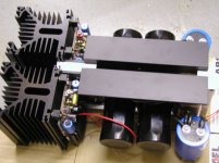
actually concerning the boards it's quite easy, i took plastic plates drilled them, then incerted electrician wire(copper) and cut some copper sheets to get the ground plan...
all the components are soldered directly on that...
looks like an easy way to replace components and quite nice as you can use a diode to lignt the plastic plate...will try to finish this amp and see about that
Vince
Hi all,
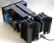
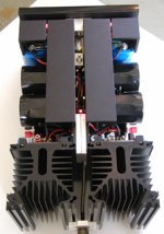
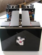
I am happy I managed to findsome time to finish correctly the whole box for the amp, here it is at least completely finished (with soft start circuit +dc velleman kit)
I included some picts ...
just for info it's now +/-24V rails and 1.2A bias
and I get 10Veff max that is about 10Watts if I measured correctly...
Cheers
Vince
Attachments
- Status
- This old topic is closed. If you want to reopen this topic, contact a moderator using the "Report Post" button.
- Home
- Amplifiers
- Pass Labs
- citation 12 mos fet