Ok. I see what you're saying. I'm glad we got that out of the way. It never occurred to me that the caps are powering everything. Now that you've told me that, it's one of those DUH! things that seems like it should've been a no-brainer...obviously not 
I double checked all the solders, and they're sound, but I've yet to find any contact cleaner to clean the connections with. I've got my fingers crossed that it's just some dust somewhere, like what happens to old speakers with attenuators in them, they get dirty over the years and it makes them scratchy, if you know what I'm talking about. Old Infinities like I use are notorious for that...
I double checked all the solders, and they're sound, but I've yet to find any contact cleaner to clean the connections with. I've got my fingers crossed that it's just some dust somewhere, like what happens to old speakers with attenuators in them, they get dirty over the years and it makes them scratchy, if you know what I'm talking about. Old Infinities like I use are notorious for that...
Hi Paco,
I don't think a can of contact cleaner will be of any help to you right now. If that stuff gets sprayed around capacitors, it tends to wick up the leads and destroy the rubber seals. It also may interact with the electrolyte and bad things happen. It can also wick into some older transistor cases - ruining them also.
Since this amplifier is old, replacing the board mounted capacitors is a good idea. This has been suggested by several members already. My approach is different, I much prefer to find the problems first. Then I go for the niceties. This ensures I did find and correct the problem.
Which leads me to the following important point. By replacing a bunch of parts, you disturb everything. Therefore, th fault may be temporarily repaired only to show up hours, days, weeks, months or years later. Gently probing and gentle heating of certain specific parts can lead you to the exact major fault (there can be more than one). Make sure everything you use is insulated, non-conducting is the best. Tapping too hard can fix the fault also, or simply excite it from every part of the board. Patience and go slowly.
Do not replace any parts before your ham radio friend can help you pick the proper components. Avoid "high end" parts and wires, take my word for it for now. Same goes for internal wiring.
The goal is to disturb as little as possible until the repair has been completed.
One tip for you. As you are tapping and changing component temperatures, it is wise to monitor both the DC output voltage and bias current. You really should have the manual or at least the schematic before you start.
-Chris
anatech .....
really dont understand why this thread is getting so long and long .....every day while we talk about one amplifier that has so much low part count ......
one dvm and soldering device and the all think will take no more than one hour .....
fact 1
all small electros ( i think maybe 4-6 ) need to be replaced
fact 2
a simple off line measure for any resistors that might be drifted from original value and replacement if needed
fact 3
while doing all that a total resoldering all over
fact 4
a good cleaning and inspection of all contacts plugs switches and so ..... a basic tuning ( with or without replacing trimers to multiturns )
and you are done !!!!!! since this sounds like an otherwise working device
i also wonder if paco 161 ever read the manual i pointed about the repairs in vintage amplifiers ..... i would really like to know since this text is composed in a very simple language and the idea was to make it usefull for people like paco .....
I'm not meaning to offend you by having not said so explicitly, but yes, I did read the link you posted. I just got fixated on something else, and haven't done anything yet with the amp. Don't get me wrong, it's extremely useful and will come in handy later on, but since Chris (or anatech, whichever you prefer I guess) chimed in, I kind of lost hope and have since decided to err on the side of caution and not pull anything apart until I have to. Besides, I personally don't know of anywhere to buy decent (or at least recommended) parts, like the electrolytic caps, resistors, etc. etc.
Sorry to do this to you again anatech, but what do you mean by heating? Same for tapping as well as using insulated what? I don't mean to be a dunce here, but probably some simple rewording might help, you know?
Also, like I said, it probably won't be for a while that I'm able to get with the guy about finding out what's wrong with the amp. Also, unless I absolutely have to, I was planning on keeping all internal wiring, just to make life easier...
Last thing, in the Citation (I'm sure you've seen one) the wires that run in the bottom section of the chassis terminate on the PCB with what look to be similar to molex pins; I was going to try and clean those off, but if you think I should skip that, I will do so...
Which leads me to the following important point. By replacing a bunch of parts, you disturb everything. Therefore, th fault may be temporarily repaired only to show up hours, days, weeks, months or years later. Gently probing and gentle heating of certain specific parts can lead you to the exact major fault (there can be more than one). Make sure everything you use is insulated, non-conducting is the best. Tapping too hard can fix the fault also, or simply excite it from every part of the board. Patience and go slowly.
Sorry to do this to you again anatech, but what do you mean by heating? Same for tapping as well as using insulated what? I don't mean to be a dunce here, but probably some simple rewording might help, you know?
Also, like I said, it probably won't be for a while that I'm able to get with the guy about finding out what's wrong with the amp. Also, unless I absolutely have to, I was planning on keeping all internal wiring, just to make life easier...
Last thing, in the Citation (I'm sure you've seen one) the wires that run in the bottom section of the chassis terminate on the PCB with what look to be similar to molex pins; I was going to try and clean those off, but if you think I should skip that, I will do so...
probably
a thing like one step at a time will apply ....here ....but still a think that this is getting out of hand ....
you had sophisticated help from anatech ,,,,,,,simplified from me and it seems that you understand neither and also you are unable to at least make up your mind ....
may be after all you should look for professional help ....
i rest my case now .... if the amp was in my lab it will be something like one hour to fix....
best regards and good luck !!!!!
Hi Sakis,
This job would be very simple for you, me or many other members to complete on our own. Hardly worth mentioning in fact. However, you forget how much you know, you have to look at this project from the viewpoint of a complete beginner. For me and possibly you, that is simply too far back in time to remember.
I think the goal here is for Paco to be able to work on this amplifier properly, and to learn what is going on. If knowledge is gained and a working amplifier comes from this, it's a huge success. Remember, he doesn't know how to properly test anything yet. There are people who can't wire a light to a switch, many in fact. So they have to get by the basics in order to even be able to read a meter and understand what it's telling them. Yes?
-Chris
Well, we had someone chime in that knows everything for one. For two, Paco is a little short on equipment and knowledge. The good news is that Paco has someone who can guide him locally. That will keep things on track.really dont understand why this thread is getting so long and long .....every day while we talk about one amplifier that has so much low part count ......
Well, Paco is getting advice from all quarters. That makes things difficult for anyone who is not comfortable with a job. This of course leads me to a point I made a couple posts ago.simplified from me and it seems that you understand neither and also you are unable to at least make up your mind
This job would be very simple for you, me or many other members to complete on our own. Hardly worth mentioning in fact. However, you forget how much you know, you have to look at this project from the viewpoint of a complete beginner. For me and possibly you, that is simply too far back in time to remember.
I think the goal here is for Paco to be able to work on this amplifier properly, and to learn what is going on. If knowledge is gained and a working amplifier comes from this, it's a huge success. Remember, he doesn't know how to properly test anything yet. There are people who can't wire a light to a switch, many in fact. So they have to get by the basics in order to even be able to read a meter and understand what it's telling them. Yes?
-Chris
Hi Paco,
Often you can make intermittent problems show up by gently tapping (very light banging) on each part with a plastic rod or handle of a toothbrush. Just listen as you tap around on each PCB board.
Heating individual components can make the problem show if tapping didn't work. You want to direct warm or cool air to one component at a time, and listen. It may take 5 ~ 10 sec. for a part to respond to the temperature change. Patience.
There are times when these methods don't work, but they are worth a try. These methods may help you find the noisy part.
Remember that chemicals are just like screwdrivers or wrenches. They are all tools and you need to use the right one. Common sense really helps here.
BTW, you can call me Chris.
-Chris
Often you can make intermittent problems show up by gently tapping (very light banging) on each part with a plastic rod or handle of a toothbrush. Just listen as you tap around on each PCB board.
Heating individual components can make the problem show if tapping didn't work. You want to direct warm or cool air to one component at a time, and listen. It may take 5 ~ 10 sec. for a part to respond to the temperature change. Patience.
There are times when these methods don't work, but they are worth a try. These methods may help you find the noisy part.
By all means, clean the contacts, but keep your cleaner off other things. Your friend can point out which components are sensitive to the cleaner.I was going to try and clean those off, but if you think I should skip that
Remember that chemicals are just like screwdrivers or wrenches. They are all tools and you need to use the right one. Common sense really helps here.
BTW, you can call me Chris.
-Chris
well
dont really know chris .... i ve tryied from my side to help as much is possible ...
in my country they say that you have to listen to only one doctor .... even if something is wrong complain to the same doctor ...not the ...next one ....
i trully hope that he manage
happy regrads sakis ....
( a bit of offtopic.... this issue we disscused about vendors place ....well i made the thread , received no email , and the thread magicly never appeared any were ..... any ideas ???)
Thanks guys for the responses. And Chris, you're right. Being essentially a complete noob to this kind of stuff, having gotten advice from many sources, it is a bit daunting to try and figure out which to follow. If I can manage to squeeze in the time tomorrow, I'll be sure to check the components like you recommended. Something else I mentioned earlier, but it probably got glossed over; the noise is only coming out of the right channel and so a visual a/b comparison of the parts between the left and right channel didn't find anything, though I'll be sure to double check that too. If I can find some cleaner I'll be sure to be careful with that.
Something I guess I should point out now is that when the amp is plugged in and I plug in a source to the right channel input, the crackling/popping/whatever skyrockets in quantity and volume, but it doesn't do that on the left. I'm not sure if that means the problem might be from the input, but I thought I'd mention that...
Something I guess I should point out now is that when the amp is plugged in and I plug in a source to the right channel input, the crackling/popping/whatever skyrockets in quantity and volume, but it doesn't do that on the left. I'm not sure if that means the problem might be from the input, but I thought I'd mention that...
Hi Sakas,
I've trained many technicians over the years, and sometimes the best thing you can do is to tell them "no, you can't handle this job". When you first started in electronics, you would have probably destroyed this amplifier trying to fix it. I probably would have. I learned by fixing things that people discarded. I still look for equipment that could not be fixed in order to keep myself sharp.
Hi Paco,
I built a jig especially for testing matched pairs for transistors and fets. It is reproduced below and is pretty easy to build and use. What you want to do with it is take your transistors with the measured beta and stick the closest ones together. Rotate some others through and use the ones that have the closest balance. You need to leave the parts in there for about 3 ~ 5 minutes. I have some foam that I place over the two transistors. Make the sockets so that you can place the two cases in contact with each other. I can take a picture of it to show you what I mean.
I get very, very good matches with this thing.
-Chris
Yes. You are very helpful. There are times when you completely forget that the average person has no interest in electronics. So, on this subject you appear to possess a vast knowledge on par with Einstein.i ve tryied from my side to help as much is possible
I've trained many technicians over the years, and sometimes the best thing you can do is to tell them "no, you can't handle this job". When you first started in electronics, you would have probably destroyed this amplifier trying to fix it. I probably would have. I learned by fixing things that people discarded. I still look for equipment that could not be fixed in order to keep myself sharp.
Yes. Hunt down Mark (= Variac) and ask.this issue we disscused about vendors place ....well i made the thread , received no email , and the thread magicly never appeared any were ..... any ideas ???
Hi Paco,
That's good thinking. You best test instruments are your eyes and your brain. I'm not kidding, although you need to program you brain for this. I'm sure you will in time.a visual a/b comparison of the parts between the left and right channel didn't find anything
Start with a dry paintbrush. Approx. 1" ~ 2" in widthIf I can find some cleaner I'll be sure to be careful with that.
That suggests a noisy transistor in the differential pair. You need to buy a bunch of replacement transistors and measure the beta. You want a matched pair of these. While you are at it, measure the diff. pair transistors on the other channel and replace those too if you have a closer match. Do not mix old with new.I plug in a source to the right channel input, the crackling/popping/whatever skyrockets in quantity and volume
I built a jig especially for testing matched pairs for transistors and fets. It is reproduced below and is pretty easy to build and use. What you want to do with it is take your transistors with the measured beta and stick the closest ones together. Rotate some others through and use the ones that have the closest balance. You need to leave the parts in there for about 3 ~ 5 minutes. I have some foam that I place over the two transistors. Make the sockets so that you can place the two cases in contact with each other. I can take a picture of it to show you what I mean.
I get very, very good matches with this thing.
-Chris
Attachments

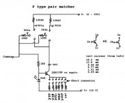
Here is the PNP matcher.
I built them both on the same perf board. One day I'll build a proper PCB for it, and a case. I use it a lot.
-Chris
Edit:
I normally use a supply voltage of 10 VDC from emitter to collector, or TP1 to TP3. I check the balance by measuring from TP1b to TP1b. I can check the base current by measuring from TP2 to common and dividing by the base resistance. Collector current is found by measuring from TP1 to V+ and dividing by the collector resistance. If you divide the collector current by the base current, you should get a number that is close to the beta at that current. To be exact, you would have to measure the divide the emitter current by the base current.
The tail current is set by shorting the pins with the resistors to negative supply. You can add them up as well by jumping more than one pair of pins. I used double row 0.1" connectors and the shorting pins from old dead computer boards.
Now, if you install only one transistor, you can measure the beta more exactly and easily for different currents. Note that you would have to measure each current setting exactly for this to be accurate.
If you build one of these, use at least 1% resistors for the collector and base resistors. Then match those as close as you can for each pair. After doing that, you now have exact values for your calculations. That is what I did. You will be rewarded by having a useful jig that will provide transistor matches that are scary close. The best part is that this jig tests the parts in the configuration they will be used in.
Attachments
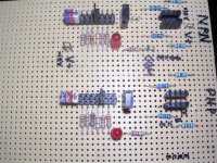
This is how it appears now.
I built this quickly as I was having trouble with simply measuring beta and sticking the transistors together. I did realize that temperature effects where one of my big problems. You have to remember that the absolute value of beta is much less important than how close they are to each other. You can also vary the tail current to check how they track each other. This jig also compensates automatically for the Vbe crowd's concerns.
One other thing I should point out. There are four lead terminals for each transistor test position. They are arranged emitter - base - collector - emitter so that you can measure Japanese parts, Pro Electron parts and the North American parts. The terminals themselves are from strips that you simply disconnect as many as you need at once. Again, they are 0.1" spacing. I make many adapters and sockets using these things.
-Chris
Attachments
Sorry I took so long to reply. I checked the parts like you suggested and there was nothing distinct I could find, but again, I'll double check later. As far as building that jig, I'm not sure I'll be able to find the time to do it around school and all, especially now that track has started too, so this may end up being stretched out for a long while. On top of that, the ham radio guy is out of town for the next two weeks, so I won't be able to get any help from him, so for the time being, looks like I'm kind of in a jam with this 
Quick question, if I could find transistors that would work with the amp that I can buy as a matched pair, would it be a good idea to do so? If I ever do get around to building that jig, honestly, I would probably only use it once...just a thought.
Quick question, if I could find transistors that would work with the amp that I can buy as a matched pair, would it be a good idea to do so? If I ever do get around to building that jig, honestly, I would probably only use it once...just a thought.
Hi Paco,
That jig is not required right now, but it would make the job of matching transistors much easier. The best thing about it is that it's cheap to build and versatile.
There is no rush to finish this project. Wait until your friend is back.
I feel you want to rush this. Don't. Take your time and learn.
You have to make up your mind on these things. You will have to invest some of your time and effort to do a good job.
-Chris
That jig is not required right now, but it would make the job of matching transistors much easier. The best thing about it is that it's cheap to build and versatile.
There is no rush to finish this project. Wait until your friend is back.
They are not sold that way for one, or the matches are very loose. I do know that NTE and ECG sell what they call matched pairs, but those matches are very loose plus the quality of the parts is low.Quick question, if I could find transistors that would work with the amp that I can buy as a matched pair
I feel you want to rush this. Don't. Take your time and learn.
If you will only fix this one amp and never build any projects, just pay a guy to repair this amp properly. That tells me you have no interest in electronics. Therefore, you will not study any further and you will not buy any equipment. A waste of your time.honestly, I would probably only use it once.
You have to make up your mind on these things. You will have to invest some of your time and effort to do a good job.
-Chris
Yeah. Let me rephrase that, I would probably only be able to use it once since I would put it away somewhere and likely loose it...which seems to happen to me very often. But yeah, no rush to get this done. Will wait for help to get back so no hurry at all...
However there is, I guess, somewhat good news. I was just able to clean off the contacts of the transistors with contact cleaner, along with the potentiometer of the right channel and the clicks and pops were almost completely gone and then I found out the hard way that the can of I cleaner I have leaks when I spilled it on the PCB, at which point the pops came back to where they were before, so it's currently drying right now. I have my fingers crossed...
However there is, I guess, somewhat good news. I was just able to clean off the contacts of the transistors with contact cleaner, along with the potentiometer of the right channel and the clicks and pops were almost completely gone and then I found out the hard way that the can of I cleaner I have leaks when I spilled it on the PCB, at which point the pops came back to where they were before, so it's currently drying right now. I have my fingers crossed...
Unfortunately, cleaner turns out to have not been the solution. I suspected a dirty potentiometer so I resoldered it and cleaned it, but no luck. However, after having cleaned the transistor contacts, as well as the pins the connect to the PCB (and allow it to be removed without cutting/soldering wires, which is VERY handy) the popping is not longer constant and now fades in and out depending on what I happen to be checking. I tried your tapping method again (I use a pencil, just FYI) and have found that if I tap on the right #1 driver (since there are two per channel) just right the popping comes and goes with varying intensity. This may or may not be the problem, but it's a hunch since I've ruled out the potentiometer on the right channel. Again, I'll just have to wait for help to arrive, which means no stereo for now
i wonder ....
how much money will cost to ship the d**** think to greece and back .....
cause if this is in a reasonable prizi i could just as well fix it for free for you .....
the way you are trying to do things either will get you nowere or it will take like a gozilion years to get this fixed ...
regards sakis


Hi Paco,
As DRC said ....
You should be using something made from plastic with no metal or any other conductor involved.
Hi sakis,
Learning is something you did at some point in your life. I'm sure it wasn't easy as some effort is required on your part. Then there are the years of gaining experience and knowledge.
-Chris
As DRC said ....
Yes! Watch out there!Don't forget, the graphite in a pencil is a good conductor of electricity
You should be using something made from plastic with no metal or any other conductor involved.
Okay, you learned something. It could be a solder joint, but is more likely the transistor. If you resolder those connections, that might temporarily "fix" the problem, but it would show up later for sure. I would replace that transistor and see what happens. Do not use NTE or any other replacement brand.I tried your tapping method again (I use a pencil, just FYI) and have found that if I tap on the right #1 driver (since there are two per channel) just right the popping comes and goes with varying intensity.
Hi sakis,
But if you did that, he would not learn anything at all. I'm closer, but I still would not make that offer.cause if this is in a reasonable prizi i could just as well fix it for free for you .....
Learning is something you did at some point in your life. I'm sure it wasn't easy as some effort is required on your part. Then there are the years of gaining experience and knowledge.
-Chris
I tried your tapping method again (I use a pencil, just FYI) and have found that if I tap on the right #1 driver (since there are two per channel) just right the popping comes and goes with varying intensity.
- Status
- This old topic is closed. If you want to reopen this topic, contact a moderator using the "Report Post" button.
- Home
- Amplifiers
- Solid State
- Citation 12 help