Hi guy´s,
has anyone a simple circuit with there i can test high power transistors as 2SC2922 and 2SA 1216.
For example a small circuit with LM317 or a L200 as power supply in that i can build in the 2922 or/and 1216 as current driver to bring them to there SOA (so 9 Ampere current) ?
Or a other simple Circuit with there i can test this Transistor up to the SOA border ?
greetings
Dirk
complete DC without other Signals.
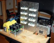
The transistor has on Emitter a resistor with 8,4 or 2 ohm with 100 to 200 watt. The transistor are passiv and activ cooled. See pic.
I have a power supply with 2*34 Volt with 9.5 Ampere and i will bring the Transistor near the SAO and will see that hold his data what stand in the datasheet.
Dirk
The transistor has on Emitter a resistor with 8,4 or 2 ohm with 100 to 200 watt. The transistor are passiv and activ cooled. See pic.
I have a power supply with 2*34 Volt with 9.5 Ampere and i will bring the Transistor near the SAO and will see that hold his data what stand in the datasheet.
Dirk
Attachments
small_boy said:Hi guy´s,
has anyone a simple circuit with there i can test high power transistors as 2SC2922 and 2SA 1216.
For example a small circuit with LM317 or a L200 as power supply in that i can build in the 2922 or/and 1216 as current driver to bring them to there SOA (so 9 Ampere current) ?
Or a other simple Circuit with there i can test this Transistor up to the SOA border ?
greetings
Dirk
Errr! No!
That is very difficult and requires very fast short pulses with low duty-cycle (<1%) at very high power.
Otherwise the transistor will be zapped in milliseconds, even if decently heatsinked.
Industrial testers use an inductive load flyback circuit to move the DUT from a saturated collector current up to a secondary breakdown.
Once, and for only about 300uS.
SOA is a calculated curve from various parameters (thermal, Imax etc) and cannot be "measured" directly.
Once up on in time (1975?) there was an application note of RCA; I can't recall wich one.
It described a test setup for a transistor tester WITH the possibility to test the SOA of a transistor.
If my memory is correct it could go up to 300V and a huge amount of amps.
It checked the temp as well, allthough I'm not 100% sure.
I rather like to find that application note again.
It was a bit expensive for me at that time to build but I can now.
If only I had that AN...
Maybe one of the older members?
(look who's calling others "older"...)
Cheers,
Zilog
@cliff
Why is then in the datasheet from Sanken for SOA one line for DC and one for Pulse ?
@zilog
I´m old (39 year at begin of February ;-)) but on 1975 i was 6 and have don´t interest for Electronics")
Dirk
That is very difficult and requires very fast short pulses with low duty-cycle (<1%) at very high power.
Otherwise the transistor will be zapped in milliseconds, even if decently heatsinked.
Why is then in the datasheet from Sanken for SOA one line for DC and one for Pulse ?
@zilog
I´m old (39 year at begin of February ;-)) but on 1975 i was 6 and have don´t interest for Electronics
Dirk
Attachments
Oh jee small_boy ,
Im 54 now, heading for 55.
If only I kept all my docs the time I as young.
You can never tell the way your life go's.
So if I may give some advice:
Never ever trow away your data books, magazines and other stuff.
One day they will come in handy.
So to the real "old" guys; look around if maybe you have that AN from RCA.
Cheers.
Zilog
small_boy said:@cliff
Why is then in the datasheet from Sanken for SOA one line for DC and one for Pulse ?
@zilog
I´m old (39 year at begin of February ;-)) but on 1975 i was 6 and have don´t interest for Electronics
Dirk
Yes, I lost 30 years worth of data books and notes in a fire

Confusing isn't it, small-boy ??
That curve says "natural cooling without heatsink", but the first break-point is 20A Ic at 10v VCE.
That is 200W.

Even with a fan cooled massive heatsink that is not real!
What do you want to TEST for SOA? If it doesn't meet SOA it dies. Period. No way back.
It is a design-aid curve.
@Tarzan :
ok ok, then i´am a young boy
@cliff :
oh thats ****.
Ok, i will test this transistors 2SC2922 with 8-9 ampere, over 1-2 hours and go near to the 200 watt Ptot to see that it don´t burn.
This is the only way to see that these transistors hold, what the datasheet says.
Because this are not from Sanken, there are from ISCSemi, and in the thread :
http://www.diyaudio.com/forums/showthread.php?s=&threadid=115281
you can read what problem i have.
A few told me, that this transistors are fakes, other that the trans from ISCSemi are ok. But now i will test it with power and look that there hold what the datasheet says.
What can i do to test this transistors and how ?
Dirk
Oh jee small_boy ,
Im 54 now, heading for 55.
ok ok, then i´am a young boy
@cliff :
Yes, I lost 30 years worth of data books and notes in a fire
oh thats ****.
Even with a fan cooled massive heatsink that is not real!
What do you want to TEST for SOA? If it doesn't meet SOA it dies. Period. No way back.
Ok, i will test this transistors 2SC2922 with 8-9 ampere, over 1-2 hours and go near to the 200 watt Ptot to see that it don´t burn.
This is the only way to see that these transistors hold, what the datasheet says.
Because this are not from Sanken, there are from ISCSemi, and in the thread :
http://www.diyaudio.com/forums/showthread.php?s=&threadid=115281
you can read what problem i have.
A few told me, that this transistors are fakes, other that the trans from ISCSemi are ok. But now i will test it with power and look that there hold what the datasheet says.
What can i do to test this transistors and how ?
Dirk
I do sympathise and you really do have a problem.
However, in my long experience, trying to test at DC is a complete waste of time. But I am not always right.
What are you going to do if they fail? The supplier will only accept THEIR test methods and not yours.
Have a look at:
SOA
particulary at the inductive test circuits.
As I said earlier, SOA curves are design aids. If you are having reliability issues and failures my first step would be to search for devices with 50% to 100% better SOA specs.
I don't think I can help more ....
Those 200W are *real*. This transistor comes in the unusual MT-200 package and is rated for 200W continuous at Tcase=25ºC, 160W at 50ºC, 120W at 75ºC, 80W at 100ºC and 40W at 125ºC.
DC SOA may be tested as long as derating due to increased temperature is taken into account. Peltier cells may come handy to keep the case at 25ºC.
DC SOA may be tested as long as derating due to increased temperature is taken into account. Peltier cells may come handy to keep the case at 25ºC.
Hi,
note that Eva's post shows the maximum powers, below the second breakdown voltage, for case temperatures @ or above 25degC.
For Tc=100degC the maximum continuous power is just 80W (2Adc @ 40Vce). This is the temperature de-rated SOA limit for a 200W, 150degC device.
Try running the device at this temperature and power dissipation and see if it survives. Remeasure hFE at various currents to see if there is any deterioration.
Now run the device a bit over 100degC at the same power dissipation (2A @ 40Vce) and see how long it lasts. Tc=110degC may last a few hours. Tc=120degC may last just a few minutes.
The results will be instructive to us all.
I still try to convince the "older" readers to have a look at their huge piles of docs and application notes.
The test setup as described by RCA was a NON Destructive (!) way of finding the soa of a DUT (Device under test)
This would be the ultime testaparatus to weed out all fake transistors from your stock and to check the new incoming.
There must be at least one copy laying around...
A link to an RCA archive?
An ex RCA buddy?
Zilog
Eva said:Peltier cells may come handy to keep the case at 25ºC.
Not really required. Take a look at this: http://www.fairchildsemi.com/an/AN/AN-7516.pdf It describes in detail a method of SOA testing without even using a heatsink. This method was originally developed by Intersil, this is the old orginal: http://www.nalanda.nitc.ac.in/industry/appnotes/Intersil/an9409.pdf Don't know if there was any similar approach before 1994...
Unfortunately, a true SOA testing bench is not something that can be easily home brewed. As others mentioned, it requires a constant (high) power pulse generator which a complex piece of equipment by itself.
Peltier junction? Even at .1C/W case to sink (and that's being optimistic) that's 20 degrees of rise. Try immersing the heat sink in an icewater bath - that will get Tc down close to 25. Testing at elevated temperatures doesn't tell you as much - remember the old Motorola app notes which specifically state "At high case temperatures, thermal limitations will reduce the power that can be handled to less than the limitations imposed by second breakdown".
With the heat sink on ice, the DUT should be able to take rated power (at the second breakdown point) for 1 second on, 10 to 20 seconds off.
With the heat sink on ice, the DUT should be able to take rated power (at the second breakdown point) for 1 second on, 10 to 20 seconds off.
Hi,
I went through my docs and found a RCA booklet with a list of Application Notes.
Here it is.
AN-6145 A Test Set for Nondestructive Safe-Area Measurements Under High-Voltage, High-Current Conditions
Any body?
Tarzan
RCA Power-Device Application Notes
General Power Applications
AN-3697 Triac Power-Control
AN-4537 Thyristor Control of Incandescent Traffic-Signal Lamps
AN-6054 Triac Power Controls for Three-Phase Systems
AN-6096 Solid-State Approaches to Cooking-Range Control
AN-6141 Power Switching Using Solid-State Relays:
AN-6286 Latching Gate-Trigger Circuits Using Thyristors for Machine Control Applications
AN-6452 A New Practical Fuse-Thyristor Coordination Method
ICAN-6182 Features and Applications of RCA Integrated Circuit-
Zero Volt Switches (CA3058, CA3059, CA3079)
Device Characteristics'
AN-4242 A Review of Thyristor Characteristics and Applications
AN-6215 Interpretation of Voltage Ratings for Transistors
AN-6272 Characteristics of RCA Monolithic Power Darlingtons
AN-6438 Surge Capability of SCR's, Triacs, and Rectifiers
AN-6456 Characteristics and Applications of RCA Fast-Switching ASCR's
AN-6624 Voltage Limitations of Power Transistors
AN-6671 Characteristics and Turn-Off Circuit Considerations for RCA GTO SCR's
AN-6687 Latching Voltage and Current in Thyristors
AN-6689 Circuit-Commutated Turn-off Time of Thyristors
Handling and Operating Conditions
1CE-402 Operating Considerations for RCA Solid State Devices
AN-4124 Handling and Mounting of RCA Molded-Plastic Transistors and Thyristors
Test/Ratings
AN-4573 Testing for Forward-Bias Second Breakdown in Power Transistors
AN-4612 Thermal-Cycling Rating System for Silicon Power Transistors
AN-4745 Analysis and Design of Snubber Networks for dv/dt Suppression in Thyristor Circuits
AN-4783 Thermal-Cycling Ratings of Power Transistors
AN-6145 A Test Set for Nondestructive Safe-Area Measurements Under High-Voltage, High-Current Conditions
AN-6163 Quantitative Measurement of Thermal-Cycling Capability of Silicon Power Transistors
AN-6281 Accurate Measurement of Sustaining Voltage of Power Transistors A Pulsed-Breakdown Test Set
AN-6330 A Safe-Area Rating System for Power Inverters Handling Capacitive and Inductive Loads
AN-6425 Automatic Analyzer for Determining Safe Operating Area of Power Transistors
AN-6800 A Test Set for Measuring hfe and fy as a Function of Collector Current
AN-6145 A Test Set for Nondestructive Safe-Area Measurements Under High-Voltage, High-Current Conditions
would be nice if this still would have somebody !
Dirk
AN 6145 is available (allmost)
I have to scan the pages and make them available.
Test setup for transistors:
Current range: 0.2 .. 20 Amps
Voltage range: 10 .. 350 Volts
Pulse width: 10 microseconds .. 2 seconds
Very impressive...
As the name of the doc is:
A test Set for Nondestructive Safe-Area Measurements under High-Voltage, High-Current Conditions.
So a bit of patience and it will be here.
Zilog
So a bit of patience and it will be here.
no problem, i can wait and the ISCsemi transis dont run away.
Dirk
Hey small_boy,
Got the AN scanned and convert each page (8) in to a pdf file.
Sorry to tell you they are HUGE in size.
An RAR file with all 8 of them is 22MB.
Each file in turn about 4.5 MB.
Contact me direct so that I can send them to you.
It needs however a seperate 300V psu.
This instrument could be a very interesting project here.
It will surely have it's use with all the counterfeit power transistors around that can blow up your expensive repair or project.
Cheers,
Tarzan
- Status
- This old topic is closed. If you want to reopen this topic, contact a moderator using the "Report Post" button.
- Home
- Amplifiers
- Solid State
- ## circuit for Transistor testing ?