found this cathode follower amp, by Fletcher and Cooke
http://www.clarisonus.com/Archives/Amp_Design/Cathode_Follower_Amp.pdf
http://www.clarisonus.com/Archives/Amp_Design/Cathode_Follower_Amp.pdf
Well if you need to by all parts again for 5-15W Circlotron Amps thats bad !
Be carefull since Circlotron OPT with relative higher Z primary coil need to be formed using split bobbin coil tehnique to obtain the best electrical ( Audio ) transfer characteristic , regardless from used type of iron core form , EI or even better double C core type .
```well, every time I believe to have learned something I only find that I know nothing, or at least still not enough``` - It is the same with me sometimes !!!")
Ps : here is one article link which describe many type of OTL PP topology , in beetwen Circlotron type too , with excellent circuits analysis :http://www.audiodesignguide.com/otl/aria.html
Best Regards
Be carefull since Circlotron OPT with relative higher Z primary coil need to be formed using split bobbin coil tehnique to obtain the best electrical ( Audio ) transfer characteristic , regardless from used type of iron core form , EI or even better double C core type .
```well, every time I believe to have learned something I only find that I know nothing, or at least still not enough``` - It is the same with me sometimes !!!
Ps : here is one article link which describe many type of OTL PP topology , in beetwen Circlotron type too , with excellent circuits analysis :http://www.audiodesignguide.com/otl/aria.html
Best Regards
Last edited:
Be carefull since Circlotron OPT with relative higher Z primary coil need to be formed using split bobbin coil tehnique to obtain the best electrical ( Audio ) transfer characteristic , regardless from used type of iron core form , EI or even better double C core type .
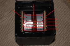
its the 'balanced' type with totally seperate windings, double C-core
too good to waste
Attachments
its the 'balanced' type with totally seperate windings, double C-core
too good to waste
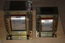
Think that 1,6K split bobbin coil OPT it is just OK for Circlotron 50W Amp with 2 x EL34 tube in AB1/B1 class , pentode connected , but what is the that OPT iron quadrature ? , heater trafo is Ok too , but main trafo is not OK for that Amp topology ! just need two galavanic separate secondary .
..... but what is the that OPT iron quadrature ?
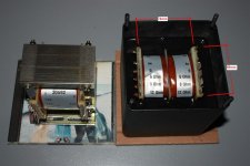
housing, cast in OPT
I think 50watt is too much for this OPT
but maybe ok in class AB, if I don't play too loud
also just now looked at power buffer amps
coupling cathodes directly to secondary
different thing tho
I will try and post about this in another thread about CFB
housing, cast in OPT
I think 50watt is too much for this OPT
but maybe ok in class AB, if I don't play too loud
also just now looked at power buffer amps
coupling cathodes directly to secondary
different thing tho
I will try and post about this in another thread about CFB
No I actually just wonder what is the effective quadrature of that OPT iron core size (Sfe ) in cm2 !?, since the effective iron core size determined lots of OPT/Amp parameters .
Interested for that power buffer amps ! I stay tuned !

Last edited:
....... effective quadrature of that OPT iron core size (Sfe ) in cm2 !?
Interested for that power buffer amps ! I stay tuned !
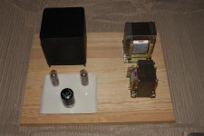
sounds great
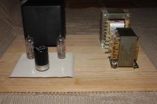
OPT plastik bobbin measures 68 x 74mm (see picture)
with housing and all, weighs in just above 3kilo
no point in denying it, I like to take pictures

Attachments
Interested for that power buffer amps ! I stay tuned !
I might be tempted to try somthing like this
but not much info to find
feel free to 'shoot it down'
though not a circlotron, its still 'cathode follower' output
if I know what that means
mind you, one reason is that I have those lowish impedance OT
Attachments
Moving the load from anodes to cathodes DOES NOT change the optimum load, just improves damping factor by a ratio roughly equal to the µ of the tubes.
And . . . do you really want to drive the screens ? or typo ?
If so, you will need to provide some very assymetrical screen current and that voids the use of capacitor links.
Yves.
And . . . do you really want to drive the screens ? or typo ?
If so, you will need to provide some very assymetrical screen current and that voids the use of capacitor links.
Yves.
Hi Tinitus !
Dont want to shut down your ideas but in your attached schematic I not understand two point !
1) Why you want to drive G2 from EL34 ?, since is already enough difficult to drive G1 of EL34 in CF configuration ! .
2) In that your topology you don`t need two separate B+ supply , single B+ well finish the job for sure .
Actually I think the best solution to use that your balanced 1,6K OPT is to consider to use old anode coupled Circlotron AMP topology with two separate but equal 250 - 300 VDC B +/ B`+ supply , and triode strapped both output EL34 tubes for best linearity , running than AMP`s output in A1 / AB1 class , and expecting than about 25 W of nice sounding tube Amp , since the anode coupled Circlotron use the whole OPT primary coil and need only half of conventional PP Amp primary coil impedance , your balanced 1,6K OPT impedance is very near for that purpose , or just perfect ! .
BTW , Viktor K. from BAT already successfully use that anode coupled Circlotron topology in BAT VK 60 Amp. but renamed to `` Single - Ended bridge Output Stage `` .
Here is the basic schematic :
Best Regards !
Attachments
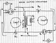
Just few more important points since I posted raw topology schematic :
1) From each of two floating B- supply you must put two equal ground reference resistors to Amps center ground star point to achieve ground reference points for PP driver stage , value of this two resistors is usually 5 to 10 time higher than value of EL34 self bias cathode resistors .
2) Since anode coupled Circlotron is formed from two basic grounded cathode SE Amps joined together G1/G1` driver peak voltage requirement is relative low , same as for conventional PP Amp .
3) Precaution must be present when you wiring two galvanic separate PT secondaries to the two greatz rectifier bridge , they have to be done in same manner ( in phase ), to avoid any hum & noises .
4) With fine triming value of EL34 self bias cathode resistors you well avoid any DC current to flow trough OPT primary coil under no signal condition .
Best Regards !
noted
and then theres the contradictory thought
that with it would be convenient to feed the PP tube amp from a balanced SS preamp
Any way, why not to try that combination? ! ,
If ocasionally that SS Preamp/Tube Amp combination sonically fail here is this DIY Audio site with many interesting DIY pure Tube balanced preamps projects !

Best Regards !
Any way, why not to try that combination? !
yep
I will 'probably' use mostly with my now old fashioned CD machine, and it also happens to have balanced out
so yeah, why not do it
alistair, yeah, I know, need two trafos with double secondary, and will build mono amps only
I have some circlotron schematics to study, and some more
FWIW the first MA-2s (OTLs) that we made were anode-coupled rather than cathode.Hi Tinitus !
BTW , Viktor K. from BAT already successfully use that anode coupled Circlotron topology in BAT VK 60 Amp. but renamed to `` Single - Ended bridge Output Stage `` .
Here is the basic schematic :
Best Regards !
something like this, in principle ?
hmm, looks almost like a blumlein thing (punctured lines)
hmm, looks almost like a blumlein thing (punctured lines)
1) From each of two floating B- supply you must put two equal ground reference resistors to Amps center ground star point to achieve ground reference points for PP driver stage
value of this two resistors is usually 5 to 10 time higher than value of EL34 self bias cathode resistors .
Attachments


- Status
- This old topic is closed. If you want to reopen this topic, contact a moderator using the "Report Post" button.
- Home
- Amplifiers
- Tubes / Valves
- Circlotron questions