Here is some info on a 2x15 and a 1x40 VU meter using an inexpensive PIC16F88. Add proper filters in front (for 1/3 octave you will need a 6-pole Butterworth for each band): www.s-o.webnode.cz/vu-meter/ E
Thank you sir.
But unfortunately the link is not working.
I got this error with the photo of the LED VU meter build. Could you kindly re-check that?
"
Sorry, the [SIZE=+0][SIZE=+0]requested page to the server could not be found[/SIZE][/SIZE]
[SIZE=+0] . [/SIZE]Probably been canceled or you have incorrectly entered the address."
Ok, here we are.
If you need the files mirrored, i can print it new.
regards Olaf
Dear Olaf,
Kindly post the mirrored files.
Also, could you kindly post the top component layers in PDF too ?
Thank you so much.
Hi Som,
sorry, was on vacation. Will later look for your files.
regards Olaf
Oh great! I hope you had a great time there. So welcome back again.
")
And please take your time.
I found a nice display section with more LEDs on youtube
10 band audio spectrum analyzer with 400 LED FullHD - YouTube
This section uses LM324 opamps.
The poster posted a documentation link there too.
YouTube
I want to use this display section along with your filter section.
It would be great if you could confirm it will work or not.
Thank you.
When you have time of course.
Hi Som
I've looked at the links and I am not a expert (thats why i built a tested solution ;-). I can not see the video in Germany, unfortunately.
I'm not sure why you do not want to use the original filter circuit for this display solution. There seems to be a simple filter circuit. If you want more frequencies, you can add filters.
By the other way you have to create a new pcb because you do not need the LM3915. I do not know how the voltage-levels are, but you can use a simple buffer for this.
Another difference is that your display is linear. the LM3915 is logarithmic.
regards Olaf
Hi Som
I've looked at the links and I am not a expert (thats why i built a tested solution ;-).
Thank you Olaf
Now you are an expert after building this. I can not see the video in Germany, unfortunately.
I'm not sure why you do not want to use the original filter circuit for this display solution. There seems to be a simple filter circuit. If you want more frequencies, you can add filters.
By the other way you have to create a new pcb because you do not need the LM3915. I do not know how the voltage-levels are, but you can use a simple buffer for this.
Another difference is that your display is linear. the LM3915 is logarithmic.
regards Olaf
That's so unfortunate.
It has a much bigger display. Some 80 Leds per channel I guess. The man has made a 10 channel display too. 10 channel is more than enough imho. The man has provided PCB layouts in Eagle format. I opened that and was able to print the pdf. But It has some errors. So I am hesitant to follow his layout. I sent a message to the man but have not got any reply from him so far.
My plan was to use your filter and buffer board along with the display of that man for his displays are bigger ( obviously at the cost of more power, some 7.5 amp )
I will attempt to build a single VU meter display following the circuit of that man and report back to you about my success or failure.
If I fail I will just use your design completely.
Thank you so much olaf. I will start making them now. And ask more if I get stuck.However, here are the files.
regards Olaf
Looks really good. Do you have a video ?
Regards Olaf
and final schematic.
Unfortunately I have no camera except my cell phone. I tried to shoot the video with the cell phone but the result is not satisfactory at all. The low frame rate of the cell phone recording is not reproducing the display properly.
I will request a friend who has a camera. If he can do it for me I will post the video and my mods here.
I used high brightness LEDs ( or what I got locally).
I used 820E resistors in series with the LEDs. In the original circuit 680E is used.
Also I found some un-routed sections in the filter board and fixed that.
Also I changed a biasing resistor from 8.2K to 33K. and 3.6M to 3.3M.
I will post everything soon. I'm still testing and fixing minor problems like improper soldering and broken tracks and level adjustment.
I am going to use the computer power supply with this since this circuit operates on 12 volts. So I will post the result too.
Just give me some time.
Hi Som,
I have seen the video. Looks very impressive. It may be that a faster display for certain music looks even better, but that's just a detail. But everything else is very nice.
regards Olaf
Thank you so much Olaf. Yes, the cell-phone camera messed up everything as I told you earlier.
I am also trying to integrate a Boom Box with Active 3 way Xover( my obsession, LOL) with this audio analyser.
I am in the process of making the Amps with 2 TDA2050 chips and 2 LM1875 chips and 2 TDA2030 chips.
I just finished making the PCBs at home today. Let's see how long it takes to complete the insane project.
I will post the final version of everything here in your thread.
Hope you will forgive me for your thread-jacking. Meanwhile kindly give me some advice/ ideas regarding the cabinet.
How did you make your enclosure?
Hi Som
there is no problem with the thread-jacking. One thing follows another, the theme is the same.
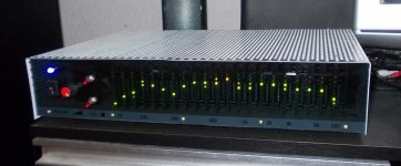
My enclosure has a front of gray plexiglass. In normal light it looks golden brown and opaque. The cover is made of aluminum, nothing special. The LEDs are in this way pleasantly dimmed so that it looks good in the living room. I will make photos next days.
regards Olaf
there is no problem with the thread-jacking. One thing follows another, the theme is the same.
My enclosure has a front of gray plexiglass. In normal light it looks golden brown and opaque. The cover is made of aluminum, nothing special. The LEDs are in this way pleasantly dimmed so that it looks good in the living room. I will make photos next days.
regards Olaf
Hi Som
there is no problem with the thread-jacking. One thing follows another, the theme is the same.
My enclosure has a front of gray plexiglass. In normal light it looks golden brown and opaque. The cover is made of aluminum, nothing special. The LEDs are in this way pleasantly dimmed so that it looks good in the living room. I will make photos next days.
regards Olaf
Thank you Olaf.
Please take your time.
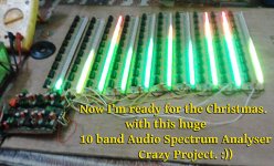
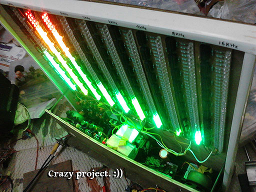
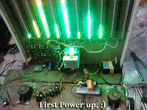
Meanwhile here are some photos of my on-going work. I added a mini boombox with this monster, lol.
http://www.diyaudio.com/forums/atta...-battery-powered-mini-boombox-final-thing.jpg
http://www.diyaudio.com/forums/atta...attery-powered-mini-boombox-crazy-project.jpg
http://www.diyaudio.com/forums/atta...attery-powered-mini-boombox-first-powerup.jpg

- Status
- This old topic is closed. If you want to reopen this topic, contact a moderator using the "Report Post" button.
- Home
- Source & Line
- Analog Line Level
- Christmas Project - Audio Analyser