A couple of notes on the formula Johan provided.
Lp = 3,2*A*µ*N²/l*10(power 8)
A needs to be modified by the stacking factor normally applied to commercial core. This number varies with usage, i.e. 1X1 interleave 0.92, 4X4 interleave 0.93, planar butt stack with out gap 0.94, with gap 0.92 and either 3 section or 4 section chunk stack 0.92. This stacking factor takes real world stamping, E/I commercial core burr and misaligned core closure into account, and unless you are an expert at soft touch core construction and the core has no burr, these numbers will apply. 33 gauge M3 will have a stacking factor of 0.95 almost regardless of type of construction.
u (i don't remember my dos keyboard commands) is taken from the core perm charts. If you need an at rest inductance, choose the perm from the far left hand edge of my graph. This is for nominal core permeability and will provide a very accurate lower limit to your inductance measured at 1 vac & 120 Hz on a typical bridge. Incidentally, US core (meaning Tempel Steel) is almost always nom to max, European core is almost always max as is Japanese core and Chinese mil grade is also nom to max. Chinese commercial core is almost never nom but is typically min to nom. Commercial core has a spread of + or - 25% on either side of nom (nominal). This is a reflection of the care in alloying, and heat treating that matches the specific alloy that is actually made, as opposed to theoretically needed. Chinese commercial core will attain US core standards within the next 5 years or so. That they are as good as they are shows how hard they have been working the problem. Not all US manufacturers were even this good, back when they were in business.
I like how Johan is providing the mathematical aspects of transformer design and so I intend to provide sidelights, details and some of the choices that need to be made when designing for power or audio. The two are basically antithetical applications of the same formulas.
Bud
Sorry, Moonbird,
My post seems to have thrown off .htm following the calc., thus for the last term: .calc.htm. (For some darn reason my pc does not want to take the whole expression including the '.htm').
Your ref output-trans-theory have been written by the same guys, Turneraudio, differing just slightly. Hope you can come right.
The reference given by Sheldon is the same as what I gave for 'Dissident'.
Moonbird,
There still remains the question of intersection capacitance. I hope I will be excused for not discussing that here, as all can be found in RDH, chapter 5.3(v); I will only be repeating. (I would hate to become like the proverbial film: Overexposed and underdeveloped.)
It will hopefully be clear that there will be capacitance between sections which will take part in attenuating high frequencies, and those will override interlayer capacitance effects between layers of the same winding. Thus a similar state of affairs will be found when calculating capacitance than for calculating leakage inductance. Only that which decreases the leakage (small spacing between sections), will increase capacitance. Thus, if somehow it is found that the figure for leakage reactance found may be increased, that is best done by increasing the isolation thickness 'c'. (RDH, fig. 5.13F). In addition, the di-electric factor of the insulation will play a role in the final capacitance - all of which will be clear from chapter 5.3(v) mentioned above.
The greatest problem with the calculated parameters, is consistency in construction. It should be understood that the process of winding a transformer is just simply, that exactitude is impossible because layers would not be perfectly flat over a flat surface. Still usefull transformers are made. My one quibble with winders is that they require some 20+ space factor, while it is possible to work to <10%. (Space factor is the difference between exact winding and that which is reached in practice.) For myself I calculate on up to 90% coverage, and then compress windings in a vice before fitting the core. (The space is there if the calculations were not faulty.) It furthermore improves efficiency to have a 'full window' instead of one through which the cat can still jump.
That must be enough from me for now. I have not dealt with the various types of core (Bud did that) - with which a further compromise appears: Does one want to pay twice as much for a small benefit i.e. diminishing returns? Etc. etc. - this brings the story dangerously close to boutique design. One should keep perspective on what exactly influences final performance of the whole, to what degree.
A number of finer points remains; I have tried to show the route successfully taken by me. It remains to point out that the graphs used and many of the procedures described in RDH, are the actual products of that titan of electronics of half-a-century ago, Norman H. Crowhurst.
Here is a good example of the help I am looking for ...
To focus this discussion a bit -- please consider the 6T4 - a low mu 7-pin tube with seeming possibilities as an output tube in a low wattage amp.
Here is a typical operating point from the NJ7P tube database:
Class A AmplifierPlate Voltage ................................. 80 V
Grid No. 1 Voltage from Cathode Bias Res ................ 150 Ω
Amplification Factor .......................... 13
Plate Resistance (approx) ..................... 1860 Ω
Transconductance .............................. 7000 µ
Plate Current ................................. 18 mA
Could someone comment on possible input impedence for the OT and why?
Might this be a candidate for an OTL design? thx.
Moonbird,
Unfortunately not. A very rudimentary calculation shows that only about 100mW could be obtained that way, with a 4,400 ohm load (single tube). A quite higher anode voltage would increase that, but one runs out of spec. before 1W is reached. You mention a low wattage amp, but I cannot guess where someone would use such a low output. Do you have any particular reason for wanting this tube?
Unfortunately not. A very rudimentary calculation shows that only about 100mW could be obtained that way, with a 4,400 ohm load (single tube). A quite higher anode voltage would increase that, but one runs out of spec. before 1W is reached. You mention a low wattage amp, but I cannot guess where someone would use such a low output. Do you have any particular reason for wanting this tube?
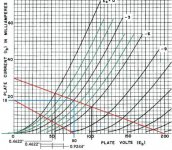
For those of you scratching your heads about Johan's posting, here are two load line curves to look over. The 6.6kz is derived from max current and voltage numbers. When brought down into the tubes operating range the halves of the AC wave form are not quite symmetrical, though quite close. The 4.4kz plot shows what Jacobs derivation produces, exactly symmetrical AC waveforms. This then will be the lowest distortion and greatest power this tube can provide. Please note where the ends of the load line stop, this is how you do one of these things, assuming you have good information, which the tube data sheet available here provides.
Frank's electron Tube Data sheets
Have fun!
Bud
Frank's electron Tube Data sheets
Have fun!
Bud
Attachments
Mmmmm .... Rather too rudimentary; erroneous! (my reply #27).
Thanks to Bud for placing those graphs. The load I used (if I am Jacob!) was the leftmost red line, left graph. Staying with negative grid voltages only, it will be noticed that the lowest the anode swing can be, will be 36V, at 10mA (rounding). That would mean a possible anode swing of 44Vpp (80 - 36) at a current swing op 10mAp. But as an output stage uses a transformer, not resistor, as load, that voltage swing is actually 44Vp and not peak-peak. (The transformer inductance allows an anode swing to 124Vp on the negative grid excursions.)
Thus the maximum output according to these figures would be (44 x 0,01)/2 (for r.m.s) = 220mW and not a rounded (because of efficiency losses) 100mW as stated previously. Apologies.
But still rather low for any practical use.
sorry Johan, it was very late at night when I wrote that note, I did catch the first Jacob, but not the second. Jacob is a nice name though,,,,
As a general rule you can count on about 48% of the DC plate voltage to be available for AC signal voltage.I have always considered this to be peak to peak voltage and use an RMS derivation when designing to gauge true AC flux density, in either push pull or single ended.
Bud
As a general rule you can count on about 48% of the DC plate voltage to be available for AC signal voltage.I have always considered this to be peak to peak voltage and use an RMS derivation when designing to gauge true AC flux density, in either push pull or single ended.
Bud
Last edited:
Moon,
Adding another tube pretty much doubles the available power. As Johan noted, you could run the tube harder, there is an indication in the graphs that a positive grid is acceptable, but I am not enough of an amp designer to help you to discover what circumstances can be concocted for that.
Regardless, you are still looking at flea power, requiring speakers with approx 105 dB per watt or better sensitivity. You are into Romy the Cat territory at that point and I would point you to his Meliguides single stage, six channel amplifier for some guidance. Romy is a Russian trained electromechanical engineer and his designs are always elegant and very well thought out. He is a person who actually understands how and why to use a ground plane, for more than it's noise shielding capability.
GoodSoundClub - Romy the Cat's Audio Site
Bud
How about PP? What would output be (guess)? thx much.
Hi Moonbird,
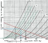
Apology for my 'absence' due to personal reasons. I have drawn a good Eb/Ib graph page for the 6T4 and done rather more precise precise arithmetic.
I may not have been clear before - at 80V h.t. the scope for anode travel is rather limited as allowed by the Vg1 = 0 curve. As said, going higher on h.t. gives more latitude. I have therefore drawn a curve for the maximum plate dissipation = 3,5W and made a different plot within that limit.
I came to an operating point of h.t. of 175V at Ip = 10mA, and a plate-plate load (in p.p.) of 6 000 ohm. The grid voltage is then -15V, with a common cathode resistor for the two tubes of 750 ohm. Under these conditions one can get an ideal output of about 2,8W. Practical circumstances allowing, an output of >2W should be available.
There is not an ideal operating point; going lower with the output impedance means higher output but more distortion. This should be mostly 2nd harmonic which should cancel in p.p., but will call for spectrum analysis of the real thing in order to arrive at a near optimum.
This does indeed bring you to a useful low output, to answer your previous question. Practical usefulness of such is still a moot point, but at least answers the original question.
Thanks much for taking the time for this analysis
Johan --
Goodness -- no apology required. You are most kind to perform this effort on my behalf -- thanks much!!
Looks promising for the 6t4 - however -- I am still not sure "how" the 6k p-to-p load impedence is derived -- which is, alas, my original question as well. I am still reading up in these areas but keep hitting walls in my understanding (if I'd have known back then what I would be interested in now -- perhpas I would have stayed longer with math )
)
I have not got a chance to play with the tool you suggested -- again -- it would appear to "need" data that I would not be able to give -- and provides an answer that I would not know how to interpret.
My practical problem is that I have a bunch of cheap TV tubes that I want to play with that have no published "load impedence" application values. I also have a number of used audio transformers I have picked up. I was hoping to find a method for at least knowing which ones to try with which tubes. I know nothing of the "core type" or "signal length" of these cast off transformers - making some of the formula provided difficult for me to interpret.
This is a very 'niche' request I can see now -- what has been so ardently offered by you kind souls is a more formal way to determine what specs to have a transformer produced for a particular application.
Once again I appreaciate the time you all have spent -- I should have asked the question more directly -- "my bad" as they say. Should also admit to all that my primary interest is guitar amps (double ) -- there are better forums to ask guitar amp questions on I know -- but IMHO (emphasis on the H) guitar amp design is in a serious rut which drives me back here. I also am interested in playing with low-wattage amps (up to 1 watt is all I need) ... ok the cat is completely out of the bag ...
Johan --
Goodness -- no apology required. You are most kind to perform this effort on my behalf -- thanks much!!
Looks promising for the 6t4 - however -- I am still not sure "how" the 6k p-to-p load impedence is derived -- which is, alas, my original question as well. I am still reading up in these areas but keep hitting walls in my understanding (if I'd have known back then what I would be interested in now -- perhpas I would have stayed longer with math
)I have not got a chance to play with the tool you suggested -- again -- it would appear to "need" data that I would not be able to give -- and provides an answer that I would not know how to interpret.
My practical problem is that I have a bunch of cheap TV tubes that I want to play with that have no published "load impedence" application values. I also have a number of used audio transformers I have picked up. I was hoping to find a method for at least knowing which ones to try with which tubes. I know nothing of the "core type" or "signal length" of these cast off transformers - making some of the formula provided difficult for me to interpret.
This is a very 'niche' request I can see now -- what has been so ardently offered by you kind souls is a more formal way to determine what specs to have a transformer produced for a particular application.
Once again I appreaciate the time you all have spent -- I should have asked the question more directly -- "my bad" as they say
. Should also admit to all that my primary interest is guitar amps (double ) -- there are better forums to ask guitar amp questions on I know -- but IMHO (emphasis on the H) guitar amp design is in a serious rut which drives me back here. I also am interested in playing with low-wattage amps (up to 1 watt is all I need) ... ok the cat is completely out of the bag ...
Last edited:
Nothing wrong with Guitar amps Moon. Some 75% of our sales are OPT's for exactly that. SLO Clone, Soldano, THD, Fortin, Club, Rhodes and a LOT of DIY builders are involved in those sales. To a degree, you can not worry about what sorts of mismatch you might find, while feeling around blindly in this venue, as almost anything can become part of a musical instrument.
However, all Johan and I have provided is really just a quick look, enough to get you into the ball park, if you want to be slightly predictive about the end results, even in a Guitar amp. Heck, for serious fooling around, we have 5 engineered "voices" that are aimed squarely at providing a certain sort of color and response envelope. Two of which allow a perfect mimic of any Marshall and any Fender, just by altering the tone stacks to that particular model. I have attached the front page of our data packet to give you an idea of what I am going on about.
Unless you are going to build, or find a tube curve generator, unmarked tubes (or ones with no data at all, and I am pretty sure you know about Frank's place, right?) you might as well fool around. Just breadboard in a way that allows you to alter the major tube control parameters and always use the high DCR side of a suspected OPT.
Bud
Attachments
More goofing in order
BudP -- You are right -- more time at the bench -- less at the computer.
Was thinking about it today -- I have a 125E and a 125SE Hammond OT. I should just connect the various primaries up to a good impedence switch and then make them part of my breadboarding setup. That way I could do a quick sanity check of impedences just to get in the ballpark. From there I could just match up the nearest DCR or impedence readings (if they have them) of my cast-offs until I found one I liked. Is that how it is done -- this "junk splunking"? Sounds more fun than is for sure. These are the big Hammond universal OTs (20 watts each) -- so I won't brake anything right - just mud and squeals right?
What is your web site buy the way -- might buy one of those Blues OTs of yours. Thanks again BudP.
BudP -- You are right -- more time at the bench -- less at the computer
.Was thinking about it today -- I have a 125E and a 125SE Hammond OT. I should just connect the various primaries up to a good impedence switch and then make them part of my breadboarding setup. That way I could do a quick sanity check of impedences just to get in the ballpark. From there I could just match up the nearest DCR or impedence readings (if they have them) of my cast-offs until I found one I liked. Is that how it is done -- this "junk splunking"? Sounds more fun than is for sure. These are the big Hammond universal OTs (20 watts each) -- so I won't brake anything right - just mud and squeals right?
What is your web site buy the way -- might buy one of those Blues OTs of yours. Thanks again BudP.
I don't have a web presence. Folks who want me find me, there is enough info out there if you are looking. I do have a couple of very good dealers though and you can PM me if or when you get serious. The Blues was called "the greatest chicken pluckin output ever" by none other than Mike Soldano, distortion king of the world.
Look here for the dealers.
Rhodes Amplification, LLC
C3Amps - ONetics Transformers & Soldano Chassis - O Netics
Bud
Look here for the dealers.
Rhodes Amplification, LLC
C3Amps - ONetics Transformers & Soldano Chassis - O Netics
Bud
Permeability Graph and DC Current Over Winding
Hi, BudP,
Here is a puzzle for you as the most advanced transformer guru.
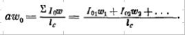
As we know, even in push-pull amplifier there is a small amount of DC current flowing through primary winding because, no matter what, output tubes can't be 100% matched and vise versa. Permeability of core changes depending on flux generated by BOTH DC and AC current. The graph attached shows value of permeability (mu) dependency of ~flux (B) and flux caused by DC current. However, the last is not measured in gauss, it is rather cryptic value (aw) measured (translated literally from Russian) in amper-turns per sm of mean magnetic path length.
Later this value used to calculate if DC current caused by imbalance of idle current in output stage is not causing saturation of core, as well as THD at lowest frequency and max output power.
Formula for "aw" is also attached, it basically sums products of I*(number of turns) divided by mean magnetic path length
The questions are - is this kind of graph available for M-series silicon steel, and if not, how to re-construct it? And how this "aw" is being called in English?
Thanks in advance.
Hi, BudP,
Here is a puzzle for you as the most advanced transformer guru.
As we know, even in push-pull amplifier there is a small amount of DC current flowing through primary winding because, no matter what, output tubes can't be 100% matched and vise versa. Permeability of core changes depending on flux generated by BOTH DC and AC current. The graph attached shows value of permeability (mu) dependency of ~flux (B) and flux caused by DC current. However, the last is not measured in gauss, it is rather cryptic value (aw) measured (translated literally from Russian) in amper-turns per sm of mean magnetic path length.
Later this value used to calculate if DC current caused by imbalance of idle current in output stage is not causing saturation of core, as well as THD at lowest frequency and max output power.
Formula for "aw" is also attached, it basically sums products of I*(number of turns) divided by mean magnetic path length
The questions are - is this kind of graph available for M-series silicon steel, and if not, how to re-construct it? And how this "aw" is being called in English?
Thanks in advance.
Attachments
Last edited:
This chart appears to be a means to predict the required geometrical construct for a magnetic core with a given flux loading. With the area of core and mean path length and permeability all as variables.
Commercial M core series has fixed two of these variables, core area and mag path length, within a center tongue width of unknown stack height. This is common E/I core in it's american standard or metric standard, path length vs center tongue width geometry.
With a fixed geometry you can use Johan's provided formula:
Lp = 3,2*A*µ*N²/l*10(power 8)
with the replacement of µ with 1/ (1 / µ + lg / lp) to arrive at
Lp = 3,2*A*N²*(1/1/µ+lg/lp))/l*10(power 8)
lg is total gap length
lp is magnetic path length
This factors in the total length of all of the physical gap(lg), which in E/I core is two times the actual material thickness of the gap material, divided by the magnetic path length (lp), added to the effective permeability of the core at it's flux load of interest, taken from those curves I posted earlier. This will provide an accurate picture of the core working in AC, with a DC current being offset by a gap vs path length structure, which is what I think your graph is pointing to. Except that your graph points to an unstructured core geometry, which you could tie down to E/I geometry if you chose to.
I know of no charts that tie this together for modern M core, though there must have been many back before the Allegheny Steel Co. standardized the industry. In my oddities collection I do have core and coils from various places that have all manner of geometries. Most especially some from Western Electric, with really wild construction.
There are not any actual permeability charts available for the M series alloys, other than M6, and even those are suspect due to the use of a non standard, non E/I core arrangement of ferrous material for the device under test. What I have provided, in it's deliberately distorted format, comes from 40 years of experience with occasional access to inductance bridges that can test a device while loaded with variable frequency, current and voltage. I am happy with them being a good enough reflection of real world core material, taken as an average of what you might actually have on hand on any given day, but they are by no means "accurate"
You can use the typical formulas for BDC and BAC to arrive at your flux load of interest, even for PP coil construction, with it's micro amps of DC offset current. The DC offset will tend to make the BH crash worse, which means crossover distortion will be higher, unless you can come up with a method of passive demagnetization for the polarity of the core, as B falls from the H saturation point. I know of one method for doing this for E/I core but have never deconstructed a c core, shell core type of core to find out if it is also applicable to them. I am theoretically sure it will work, assuming that my postulated event is happening as I think it is, but the physical torture of disassembling and reassembling one of those wound and cut cores is way beyond my level of practical interest.
If you want to pursue your interest, I would suggest the Allegheny Steel Co "Magnetic Core Material Practices" book from 1937. I do have a PDF of this, if you want to provide me with an email address in a PM. It is only 9.2mb of data and will give you much more accessible information for your investigations than is found in any other source I know of.
Bud
- Status
- This old topic is closed. If you want to reopen this topic, contact a moderator using the "Report Post" button.
- Home
- Amplifiers
- Tubes / Valves
- Choosing an output transformer