No problem, I often use what I have. It forces innovation.
6dB of bandpass ripple isn't so much innovation as abomination - and with specs that are almost certainly not as advertised. How does the box look with Fs, Qts and Vas varied +/- 20%?
yes, those previous ones were a bit bumpy. However that 6db ripple may be tiny when you see what room modes will do to it.
Costs only a little effort to see what is possible") then decide if its acceptable.
then decide if its acceptable.
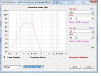
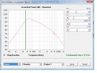
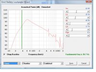
Here's another, but the range is reduced to get lower ripple @67L.
Costs only a little effort to see what is possible
then decide if its acceptable. Here's another, but the range is reduced to get lower ripple @67L.
Attachments
I have the subwoofers already. I have a Planet Audio 1500.1 and it is stable down to 2 ohms.
I always wonder how these amps manufacturers quote these "generous" power capacities. This one claims 1500W, but that's probably just "instantaneous".
Another opinion on its capacity. It has a 25A fuse, so raw input power is 12DVC*25= 300W max continuous input. It has a SMPS to boost the voltage so 85% efficiency provides 300W * 0.85 = 225W available. It has a class A/B output which are typically 65% efficient so 225W * 0.65 = 165W available assuming the rest of the unit uses minimal power. After that, we would need more detail because it will further reduce from the actual load impedance and acceptable distortion. Still, you can probably get 100w into a 3 ohm load from it. That should be enough to reach 105dB from a 90dB/w sub.
No problem, I often use what I have. It forces innovation. Everything is fair game if you can make it work.
Preferred HT sub should have lower Qts=9mm . There are lots of subs that meet this criteria. They are better suited to ported boxes and allow more linear travel (less distortion). Have a look at my BP6 using DCS305 (budget sub) SonoTube and SewerPipe BP6 Subwoofer and notice its flatter, wider and lower freq with similar 60L . That link has the design prediction and measurements.
HornResp is fairly easy to use, and you can adjust the design type, swap drivers, and get a pretty good idea of how your system will perform before any cash is spent.
In addition to your car amp, you will need LP filters that may (or not) be in your existing main HT amp. You will also need HP filters to prevent VLF and excessive woofer excursion as your Xmax=4.7mm is on the short side.
And how much volume am I supposed to put per chamber since there are two Chambers for the bandpass 6th order and what are the tunning freq
Last edited:
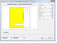
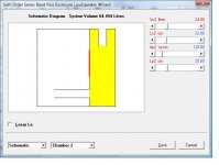
I've attached pics that show chamber#1 and chamber#2 highlighted in yellow. The parameters are listed in the upper right side. There are many ways to physically make this design. All of the parameters can be adjusted, depending on what you want or have on hand. HornResp allows you to adjust pretty much everything.
First and foremost, you should try out HornResp. I've included a design file that I was playing around with. As you add restrictions like depth, or available pipe diameters, you will need to adjust other parameters to get a workable design. So far we've only talked about frequency but there are other things to consider before you break out the power tools and glue. Is the possible, also acceptable.
First and foremost, you should try out HornResp. I've included a design file that I was playing around with. As you add restrictions like depth, or available pipe diameters, you will need to adjust other parameters to get a workable design. So far we've only talked about frequency but there are other things to consider before you break out the power tools and glue. Is the possible, also acceptable.
Attachments
Last edited:
yes, those previous ones were a bit bumpy.
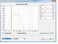
Now turn on the pipe resonances
I've attached pics that show chamber#1 and chamber#2 highlighted in yellow. The parameters are listed in the upper right side. There are many ways to physically make this design. All of the parameters can be adjusted, depending on what you want or have on hand. HornResp allows you to adjust pretty much everything.
First and foremost, you should try out HornResp. I've included a design file that I was playing around with. As you add restrictions like depth, or available pipe diameters, you will need to adjust other parameters to get a workable design. So far we've only talked about frequency but there are other things to consider before you break out the power tools and glue. Is the possible, also acceptable.
I was also looking at other boxes types and I was seeing that this box has a little bit of a radical frequency curve compared to other boxes other boxes are flatter but this gives a little bit of a higher output when it comes to only two frequency ranges. I have attached a picture that show this box type compared to others which are the flatter ones. Or is there something I'm not getting?
I downloaded Hornresp and it looks very complicated I almost don't understand any of the abbreviations.there's a different learning curve when it comes to this compared to WinISD

Last edited:
I was also looking at other boxes types and I was seeing that this box has a little bit of a radical frequency curve compared to other boxes other boxes are flatter but this gives a little bit of a higher output when it comes to only two frequency ranges. I have attached a picture that show this box type compared to others which are the flatter ones. Or is there something I'm not getting?
I downloaded Hornresp and it looks very complicated I almost don't understand any of the abbreviations.there's a different learning curve when it comes to this compared to WinISD View attachment 647358
The BP6 in your WinISD is a parallel tuned version. The one I used in a BP6 series tuned. In your design, the peak can be reduced by increasing Chamber#1 volume, or decreasing port#1 diameter, or increasing port#1 length.
There will be a learning curve to any tool. If you are comfortable with WinISD then it should give you similar results as well.
Last edited:
I took a step back and looked at what other people do with this sub. There are some design examples at Pioneer TS-W304R Champion Series 12" 4-ohm subwoofer at Crutchfield.com and when I use these recommended sizes for sealed or ported boxes I get poor results. It could be that being in a car (reduced volume) is compensating or maybe they are just meant to be "thumpy".
I've used the recommended box sizes and tunings and posted the responses. First one is a sealed box and the second is a ported (BR) box. I would not like either of them for HT unless you have a way of EQing them flatter in the 30Hz-100Hz range.
I've used the recommended box sizes and tunings and posted the responses. First one is a sealed box and the second is a ported (BR) box. I would not like either of them for HT unless you have a way of EQing them flatter in the 30Hz-100Hz range.
Attachments
Last edited:
In a 2 cubic foot sealed box, you have a Qtc ~1.0 and an F3 of ~35Hz.
This is actually fine as far as subs go, and your "boom car" sub doesn't have the excursion to usefully go lower anyway.
With a vented box jammed into a smaller than typical sized box you gain very little over a sealed box. To get useful gains from vented you need a much bigger box than 2 cubic feet with this woofer. Model the 7 cubic foot box I described earlier and compare it to a smaller box tuned to the same frequency.
For a vented box in a home, having a woofer with Qts>0.5 is not useful. It is quite plain in your models, but you are not able or willing to see it.
For a vented box design, find a better woofer, one with a Qts~0.4 and an Xmax more like 12-15mm. Run some models and compare them to your woofer. Something like this:
Dayton Audio RSS315HF-4 12" Reference HF Subwoofer 4 Ohm
It will model a lot nicer.
DonVK, I have read this thread.
The OP is stuck on vented and unwilling to consider anything else, and it is obvious from the WinISD screenshot that there is no understanding of physics or box design behind what was done. The woofer doesn't model well because it wants a larger box due to the high Qts.
The actual parameters of a woofer in this price point may differ significantly from spec, and some optimized 6th order will be very dependent on parameters and also on tuning/adjusting skill the OP obviously doesn't have.
Thanks for adding, @bjorno
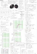
Your calculated, and cross checked T/S parameters look very close to Pioneer's spec'd numbers.
Are you including the Linkwitz transform to get your posted FR graph, its not clear.
Why is the HornResp prediction (for 42L bass reflex) so different than yours ?
Your calculated, and cross checked T/S parameters look very close to Pioneer's spec'd numbers.
Are you including the Linkwitz transform to get your posted FR graph, its not clear.
Why is the HornResp prediction (for 42L bass reflex) so different than yours ?
DonVK, I have read this thread.
The OP is stuck on vented and unwilling to consider anything else, and it is obvious from the WinISD screenshot that there is no understanding of physics or box design behind what was done. The woofer doesn't model well because it wants a larger box due to the high Qts.
The actual parameters of a woofer in this price point may differ significantly from spec, and some optimized 6th order will be very dependent on parameters and also on tuning/adjusting skill the OP obviously doesn't have.
Why are you assuming I'm unwilling to try other things. You're basing me off of things I've never said. Based on a screenshots I have tried other boxes and I'm modeling other boxes after the help I was given by the another poster.
@RonE : Read post #20.
No one is saying this is a good sub for HT.
The OP has these subs already and is wondering if it is possible, with any design, to make it work. There are very few options, none are ideal, we all see the obvious.
This is extremely overwhelming right now I will read over what you have suggested me in the past few comments tomorrow. Some of what the other guy suggested
Hi All,
FYI:
b
Hi bjorno,
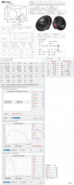
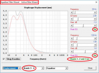
I assume that the image attached below, taken from your post above, is a montage constructed from at least three different screen prints?
Otherwise I am at a loss to explain why "Equaliser Filter Wizard" and "Active Filter Wizard" should both be shown in the filter wizard form caption together, and why equaliser bands 3 and 4 appear to be switched on when the note in green says "Bands 1, 2 and 3 on" (band 4 excluded).
Would appreciate any clarification - many thanks.
Kind regards,
David
Attachments
Hi bjorno,
I assume that the image attached below, taken from your post above, is a montage constructed from at least three different screen prints?
Otherwise I am at a loss to explain why "Equaliser Filter Wizard" and "Active Filter Wizard" should both be shown in the filter wizard form caption together, and why equaliser bands 3 and 4 appear to be switched on when the note in green says "Bands 1, 2 and 3 on" (band 4 excluded).
Would appreciate any clarification - many thanks.
Kind regards,
David
Hi David,
Thank you. I deserve that comment from you(or anyone) after scrutinizing my bad Cut and Paste (Postings).
Its not the first time or I managed to confuse.
You’re right the Screen Plot is constructed from at least three different screen prints.
First my Cut and Paste flow was by making the PEQ 1 and 2 Screen= On then Screen for 3 but 4= Off.
I attempted to merge 2 Screens into a single: Band 1-2 back into the Screen for Band 3-4 but I didn't notice the inconsistency that occurred with label 3-4 so Band 3-4 should be labeled Band 1- 2 and Band 3-(4 Off) should be placed outside at the right side.
I may have done this before in other submitted HR simulations, without any hesitation. The resulting FR plot is at least correct but sorry for the confusion I made.
b
- Status
- This old topic is closed. If you want to reopen this topic, contact a moderator using the "Report Post" button.
- Home
- Loudspeakers
- Subwoofers
- Choosing a tuning frequency