Is this the way one should do it?
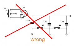
Not quite. You have shown all the capacitors with a ground connection. Only the last one (C22 in your example) should have the ground connection, otherwise the ground is acting as a short circuit across the inductors. You also need to show where the centre tap of the transformer secondary goes - it should go to the negative terminal of the first capacitor (C20).
I thought so. Thanks. This is actually as I had drawn it initially.Only the last one (C22 in your example) should have the ground connection
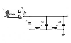
Do you mean even when it is correctly wired as below?Should a choke go open circuit you could end up with high volts on the input jack ground and kill someone.
Attachments
Last edited:
Hi!
I read about one disadvantage of this approach:
You have some stray capacitances from the transformer secondary to the core and thus to ground. This stray capacitance is in parallel with chokes in the ground return and thus bypasses them.
How relevant this effect is? I don't know. Your chokes have some winding capacitances too. So it probably depends on the transformer.
I'd get proper chokes which can handle the voltage.
Best regards
Thomas
Ah...never knew this. I thought this approach had no drawbacks.I read about one disadvantage of this approach:
I may be wrong, but the schematic in post 4 does not look correct to me.
The transformer center tap must go to the first (left) inductor.
Should a choke go open circuit you could end up with high volts on the input jack ground and kill someone.
Not if the grounding is done correctly. You would actually end up with a high negative voltage on one side of the faulty choke, and on the negative end of those components preceding it (capacitors, other choke, as applicable). The ground would still be ground, and the HT would not be HT.
Does this method affect the amount of capacitance "seen" by the rectifier? Ie: does the first choke in the ground run isolate the caps after it from the rectifier as it would if the choke were in the HT line? If not, I could see this as a major gotcha what with exceeding maximum capacitance for a valve rectifier.
Does this method affect the amount of capacitance "seen" by the rectifier?
No
Thomas
I read about one disadvantage of this approach:
You have some stray capacitances from the transformer secondary to the core and thus to ground. This stray capacitance is in parallel with chokes in the ground return and thus bypasses them.
Some PT's have an electrostatic or protective screen between primary and secondary, and the screen is normally grounded to chassis. The capacitance from secondary HT to screen may conduct mains frequency and diode rectifier related noise depending on the winding section next to the screen.
Similarly, edges of winding layers and the outer layer (usually the secondaries are on the outer layers) have parasitic capacitance to core (and hence to chassis).
Effectively, the filter capacitors are short circuits to mains and higher frequency noise, and such noise currents simplistically loop via the stray parasitic capacitance to chassis to star ground and back to the secondary windings via the CT and diodes. The chokes per se are not going to significantly suppress this form of noise, or affect it.
Any additional common noise on the B+ due to this connection can be easily dealt with - since it's primarily high frequency noise, a small RC section in the positive lead will handle it. or put one choke in negative lead, one in positive.
It's a series circuit, so order of components doesn't matter (to first order).
It's a series circuit, so order of components doesn't matter (to first order).
Hi!
I read about one disadvantage of this approach:
You have some stray capacitances from the transformer secondary to the core and thus to ground. This stray capacitance is in parallel with chokes in the ground return and thus bypasses them.
How relevant this effect is? I don't know. Your chokes have some winding capacitances too. So it probably depends on the transformer.
I'd get proper chokes which can handle the voltage.
Best regards
Thomas
Sounds different too. I tried variations of this with both single winding chokes and Lundahls in their common mode configuration. It was years ago and my preferences may have changed since then but at the time I didn't like what I heard. I remember the common mode connection in particular made the circuit sound smooth but lacking life - a little like the effect of voltage regulated filaments.
") flame Not an EE but my thought was that putting resistance in the return to the rectifier might not be a good thing. That's how I left it anyway.
flame Not an EE but my thought was that putting resistance in the return to the rectifier might not be a good thing. That's how I left it anyway.WWW.The State Department could use a man like you . . .I may be wrong, but the schematic in post 4 does not look correct to me.
Oh, you'll find that the transformer centertap will have a DC voltage of something like 15V, with lots of ripple. Depending on choke inductance, resistance and current draw off the B+. You probably don't want to use this 15V for anything, as there is that hazard if the chokes ever go open...
noShould a choke go open circuit you could end up with high volts on the input jack ground and kill someone.
Does this method affect the amount of capacitance "seen" by the rectifier? Ie: does the first choke in the ground run isolate the caps after it from the rectifier as it would if the choke were in the HT line? If not, I could see this as a major gotcha what with exceeding maximum capacitance for a valve rectifier.
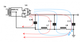
rectifier currents go red lines, not blue
----------
this connection has one big benefit, it´s the Umax winding-iron insulation.
supply chokes are often low resistance (across winding), low U drop animals, therefore risk of breaking winding is low
spike across winding could occur with silicon diodes during startup (empty caps, 0 ohm & no softstart), but then put varistor to be sure
but that will happen no matter where you put chokes
Attachments
- Status
- This old topic is closed. If you want to reopen this topic, contact a moderator using the "Report Post" button.
- Home
- Amplifiers
- Tubes / Valves
- Chokes in the ground "plane"