I made several Transformer testers. just two big 3000ohm 200 watt pots and a 10 ohm resistor to check current draw.
I can test: choke input, bridge rectifier, center tap transformers and voltage Doublers. Can test at any current draw. very good if you need to drop voltage just put small caps before the choke input and increase cap size to get higher voltages.
Much more accurate than doing simulations. I have a lot of ex military power transformers to test.
Phil
.
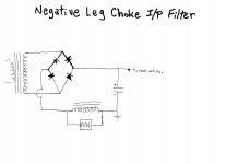
I had occasion to upload the attached "hen scratch" graphic over on AA. It seems that it is useful here too. Measures have to be taken when choke I/P filters are combined with SS diodes, to avoid destruction by inductive kick back spikes.
A high current supply is needed for a PP 6550 stereoblock. A pair of sockets are needed for 2X 5R4s, which will turn on almost as quickly as "sand" does. Since 2 sockets are a given, consider using a pair of damper diodes, which start slowly, for B+ rectification. The 6CJ3 is a "monster" and a pair will comfortably supply 600 mA. of B+. The Tube Store has 6CJ3s and the Novar sockets they mount in at reasonable cost.
The SAFE way to employ damper diodes is to tie each cathode to an end of the heater and energize the heaters with a dedicated filament trafo that has a superior HIPOT rating. Triad's VPL12-4000 fills the requirement and is favorably priced. When I checked Mouser a few hours ago, they had 2X VPL12-4000s in stock.
Attachments
Hi Eli,
So, you are saying to use two 6CJ3s to form a full wave? Novar sockets are no big deal. I have a quad pulled from an old Fisher amplifier. Probably a NOS quad of sockets also. The main issue is where to put that Triad.
The 6CJ3 is OK to use with a 1200VCT power transformer?
Use the triad to power the filaments on the 6CJ3s and the power transformer filament winding for the power and driver valves?
Blair
Last edited:
The 6CJ3 is OK to use with a 1200VCT power transformer?
A 1200 VCT rectifier winding needs diodes whose PIV is not less than 1698 V. You always leave yourself some breathing room. So, call 2 KV. whats needed. The PIV rating of the 6CJ3 is a whopping 5.5 KV., design maximum.
 "It's a piece of cake."
Take a look at GE's 6CJ3 data sheet. Notice the remarks about a diffusion bonded cathode, which is highly resistant to stripping. There is every reason to believe that 6CJ3s will have lengthy service lives.
Use the triad to power the filaments on the 6CJ3s and the power transformer filament winding for the power and driver valves?
Correct! If the power trafo has a 5 VAC winding, voltage multiply it to get the bias (C-) rail.
I'm only mentioning because your questions make it seem like this is your first choke input supply and it's kind of a doozy of a first and it looks like you'll be trying it out in the case.
I'm sure you know but the supply rises to 1kV + if unloaded (I don't know the arc length of 1kV). If you have your heart set on it then I wish you the very very best with it.
Like theGimp says definitely model it. You can put in the range of loads the supply will see too and see the performance with various chokes as well as SS vs tube rectification. And nothing goes boom. Of course nothing beats trying it out to see what happens for accuracy.
I'm sure you know but the supply rises to 1kV + if unloaded (I don't know the arc length of 1kV). If you have your heart set on it then I wish you the very very best with it.
Like theGimp says definitely model it. You can put in the range of loads the supply will see too and see the performance with various chokes as well as SS vs tube rectification. And nothing goes boom
. Of course nothing beats trying it out to see what happens for accuracy.I'm only mentioning because your questions make it seem like this is your first choke input supply and it's kind of a doozy of a first and it looks like you'll be trying it out in the case.
I'm sure you know but the supply rises to 1kV + if unloaded (I don't know the arc length of 1kV). If you have your heart set on it then I wish you the very very best with it.
Like theGimp says definitely model it. You can put in the range of loads the supply will see too and see the performance with various chokes as well as SS vs tube rectification. And nothing goes boom
Yes and no. I've built dozens of amps and "tuned" B+ with C1 in front of the L1. Nothing this high voltage though. Mostly in the 350-500V range.
It has always been iron that was negligible also. I'm building these for me, so it's a bit more important
Kind of a no compromise type thing. Lots of $$ bolted to the plate, so I want to ask the right questions.
I can certainly see the investment. I don't mean to be a drag on your project. Having a choke input filter doesn't add to the no compromise part necessarily. But if you're all good to go with the rating on your transformer and your bleeders are secure and well over rated. It looks like you're going to get excellent advice. Then all I can say check everything over and over and be careful. Sorry, I can't help myself.
. Sorry, I can't help myself. The power transformers were purchased for another project to have a higher B+. I should probably have sold them and got appropriate power iron, but these things are tanks! They weigh a solid 17-20lbs. They will deliver at least 300mA, but more like 450-500mA.
As for checking everything. That's what variacs and multiple meters are for
That's what variacs and multiple meters are for
That's what I know too. I had a scary experience with one of those once. Took a month off of self scolding. Now I bolt everything and screw everything down. -Fred
edit: choke input was the experience. Very scary indeed and a bit expensive.
Last edited:
Hi,
The amp is a PP monoblock using 6550s idling at 55mA per tube if B+ of 450-500V is achieved without smoke.
Damper diode rectification and choke I/P filtration will bring the rail in somewhere in the vicinity of 525 V. It is customary to follow the initial LC filter section with an additional filter section. This situation calls for that section to be RC. The stock value of 150 Ω should be OK. Use 50 W. rated wire wound parts and ventilate well.
The 1st (only) inductor in a choke I/P filter takes a BEATING. Hammond's 193Q might be up to this job. However, I would not be surprised to hear that a small amount of "fudge factor" capacitance was needed to control "singing". The "fudge factor" cap. goes in what would be the 1st position of a CLC filter. Use the smallest amount of capacitance that tames the buzz, but don't exceed 0.47 μF. If 0.47 μF. doesn't control "singing", the choke is unsatisfactory. It might be better to simply order inductors from Heyboer that are specifically designed for choke I/P service and can pass at least 300 mA. of B+.
Hi,
The amp is a PP monoblock using 6550s idling at 55mA per tube if B+ of 450-500V is achieved without smoke.
So, 110mA at idle, plus whatever the previous stages draw. What is the max current (or target power output)? I'm guessing around 300-350mA or so? You shouldn't need a bleeder, aside from what one would normally use across the filter cap(s), since the idle current is nearly 1/3rd the full load current.
You said the trans is 1200 VCT and the choke is 10H. If you measure the dc resistance of the transformer primary, HV secondary, and the choke, you can simulate the PS with a reasonable degree of accuracy. Accuracy is improved if you measure the unloaded secondary voltage of the trans.
I ran a quick analysis using models of transformers and chokes that I have. In this case, the trans secondary is 1200VCT with a resistance of 160R (80R per side), the choke has a DCR of 63R, the filter cap us 40uF, and the rectifiers are 6D22S damper diodes. At 103mA current, the output is 517V with 3V p-p ripple. Increasing the load to 385mA drops the output to 462V, still with only 3V p-p ripple. That equates to a regulation of about 11% over a 3.8:1 ratio of current. Not too bad. Most of the drop is due to the I2R losses in the trans and choke. The 6D22S only accounts for about 16-17V drop at full load. Using SS rectifiers would give around 522V at idle and 478V at full power, or about 9% regulation.
Just for grins, I did the analysis for a cap input supply using SiC rectifiers. Same trans, with a 500uF filter cap. Idle (103mA draw) voltage was 792V. Loaded (385mA) voltage was 715V. This gives a regulation percentage similar to the choke input supply with damper diodes. The downside is the amplitude and spectrum of the ripple. It is about 1.5V greater than the choke input, and consists of sawtooth waveforms (which are rich in harmonics) rather than the nice sinusoids of the choke input supply. Worse yet is the difference between the waveforms in the transformer windings. The choke-input supply gives approximately square waveforms in the trans, with a peak magnitude of 425mA. The cap-input gives short, high current pulses with a peak magnitude of 1.6A! This increases both copper and iron losses in the trans and worsens the power factor of the supply.
Overall, regulation of any passive PS is heavily dependant on the DCR of the magnetics. Swinging chokes are often used because they have less DCR than an equivalent size gapped choke, which improves regulation. Resonant choke supplies are another solution commonly used in amateur radio linear amp supplies, but I wouldn't use them in an audio amp for several reasons. Cap input supplies can use a lower secondary voltage for a given DCV, which means fewer turns of larger wire and thus less secondary resistance for a given VA rating. Since cap inputs should use a higher VA trans for a given output current (due to poor power factor), that means even lower DCR. In the end analysis, either will work, but the cap input will be cheaper while the choke input will be electrically quieter and give a cooler running trans. And you can use damper diodes without a serious performance penalty, which is always cool
Also, the meager cap requirements for the choke supply means you can easily use film caps rather than electrolytics, which is A Good Thing™.
Last edited:
If you're running without a bleeder and you want to do some tube rolling on your power tubes (could be fun), when you power back up your damper diodes are still warm and your power tubes are cold. Bam! I'd keep the bleeder jusr for the "idiot factor" which, being an idiot myself, is the advice i can give.
Not sure what happened to my post, but here is a preliminary drawing.
DCR of power transformer secondary is 61ohms/side
L1 is 55ohms
L2 is 23ohms
This PS is based on my interpretation of this thread. It may be all wrong
DCR of power transformer secondary is 61ohms/side
L1 is 55ohms
L2 is 23ohms
This PS is based on my interpretation of this thread. It may be all wrong
An externally hosted image should be here but it was not working when we last tested it.
- Status
- This old topic is closed. If you want to reopen this topic, contact a moderator using the "Report Post" button.
- Home
- Amplifiers
- Tubes / Valves
- Choke ratings and resistor values in choke input supply?