mikelm said:...I'm interested if you or others have ever tried 4.7uF directly across the secondary in a normal supply.
No one ever seems to comment when I mention this idea which I find strange becauce this is the best, easiest tweek I have ever discovered. no matter what cct I have tried it on, it has always made a big improvement.
From simulations it seems that 4,7uF across the plus and minus of the bridge is more effective than across the AC inputs (= the secondary of the transformer). Smaller values (100n-1u) do work, but often require another bigger capacitor (470n-10u) with series resistor in parallel as a damper. Ratio of C's approx 5-10, resistor value depending on the inductance of the transformer secondary and the value of the C, but in the range of 5-15 Ohm.
Optimum value of the resistor in series with the biggest C is approx sqrt(L/C) with L is the secondary inductance and C the value of the smaller C. Your 4.7uF seems big enough to allow for a value of R that is close to the series resistance of the secondary, so effectively the LCR is dampened already. This is a nice advantage of such a big C: it makes everything less critical. A kind of cure for all, as you already noticed.
At least no additional C's across each diode of the bridge are required anymore, neither expensive FREDs.
Steven
Steven said:Your 4.7uF seems big enough to allow for a value of R that is close to the series resistance of the secondary, so effectively the LCR is dampened already....
At least no additional C's across each diode of the bridge are required anymore, neither expensive FREDs.
I would have thought that the fact that the secondary is inductively linked to the mains via the primary would have big damping effect upon any potetial ringing in the secondary. The 4.7uF cap would enhance this by reducing frequency of ringing to a value where the inductive coupling is still strong.
What is a FRED ?
I have a question about diode. I built smps for audio, about 30khz. The usual dioda used is ultra fast type, like BYW29 or MUR1610.
There is a kind of dioda called Schottky. Usually the rating is low, below 40V, but it is said faster than ultra fast diode.
Have any one tried, is there any improvement in sound, if we use schottky instead of ultrafast dioda?
Actually what is the logical explenation if someone said that using a certain kind of dioda compared to other type of dioda gives a better audible difference?
The schottky dioda is only 40V max rating, what symmetrical value can I built with this dioda? Can it safely built a bridge rectifier of +/-40VDC? If it cannot, what is the max symmetrical value can be built with a certain dioda voltage rating?
lumanauw said:Actually what is the logical explenation if someone said that using a certain kind of dioda compared to other type of dioda gives a better audible difference?
that's for our golden ear friends to answer.
schottky diodes (they aren't really diodes as in the normal sense) have much lower forward voltage drop. so at given current flow, it dissipates much smaller current.
it can also work at very high frequency. Mostly used in switching power supplies.
Frederico, Not quite sure what you mean when you say 'small enough'...
With reference to post #14 by Steven. As he correctly states a choke input filter has a VDC=0.9 * VacRMS (about) while a cap input one has a VDC= 1.41* VacRMS, if they are well designed.
However one can put a little cap. before the choke and preserve the DC voltage (0.9*VAC) . If I increase the value of the cap , at some point the VDC starts to increase and I stop.
Some people do this (especially with tube amp) . Why? They said that the input choke is too much
stressed and that the little cap before it reduces this stress preserving the good performance of an input choke filter. I do not agree with them, however. Simulations show to me that the presence of the (little) cap marginally changes the shape of the current in the choke while the current in the diodes is greatly altered with the presence of high peaks that I want to avoid since I think that is better if current is drawn from the mains in a smooth way.
Bye
Federico
HELP !!!
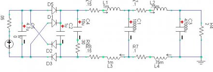
I'm now in the process of building the cct below that I posted earlier.
What I am stuck on is getting my head round where to start with the chokes.
I don't really have any idea how large the cores need to be to avoid saturation and what size gap I will need.
They need to be able to deal with 6A DC.
The pairs of chokes in each leg are inductively linked therefore total inductance is doubled. i.e. 4mH & 3mH
Should I try 200VA cores as a starting point ? or do I really need to be looking at 1000VA cores to realise this design without compromise ?
Air cores I think would be too big and probably unecessary in this PSU.
God how much are these things going to weigh ?
Attachments
Just for comparison, look at http://www.mundorf.com/english/bauteile/frspule.htm and from there to the transformer shape section in the menu. These coils are wound on the E-section only, without the I-section. They will not easily saturate and the size is given for different inductance versus resistance values.
If you use the additional I-section with air gap the inductance will become higher, but saturation might occur.
Steven
If you use the additional I-section with air gap the inductance will become higher, but saturation might occur.
Steven
- Status
- This old topic is closed. If you want to reopen this topic, contact a moderator using the "Report Post" button.
- Home
- Amplifiers
- Solid State
- Choke for Pi Filter