Hello good folks on the board,
I have a nice one here. A local church in the dominican republic bought a real Peavey amplifier. Only the sound was "no bueno"
If they hear that over here, there is something seriously wrong.
And there is! A local repair shop took out the original peavey electronics and build in two chippy chappy boards.
..............................................
And so, i'm trying to make something of it by:
Just by applying the rules for electronics (good cables)
earth grounding (does an amp need that?)
good soldering
a diagram
a DC protection
an output filter
Cooling of the drivers (they are not cooled...)
And if you folks have a remark about the electronics: SHOOT!
my first impression:
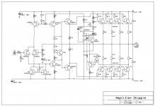
first of all: The capacitor C2 seems to be a big one for feedback.
R3 doesn't have a capacitor parallel
the protection circuit around the thyristor puzzles me.
There is no thermal stabilisation. What component is influenting the thermal behavior more? The triple rectifiers or transistor T20?
Good things:
The power transistors are ok
Let's make this a holy ampie again
Koert.
I have a nice one here. A local church in the dominican republic bought a real Peavey amplifier. Only the sound was "no bueno"
If they hear that over here, there is something seriously wrong.
And there is! A local repair shop took out the original peavey electronics and build in two chippy chappy boards.
..............................................
And so, i'm trying to make something of it by:
Just by applying the rules for electronics (good cables)
earth grounding (does an amp need that?)
good soldering
a diagram
a DC protection
an output filter
Cooling of the drivers (they are not cooled...)
And if you folks have a remark about the electronics: SHOOT!
my first impression:
first of all: The capacitor C2 seems to be a big one for feedback.
R3 doesn't have a capacitor parallel
the protection circuit around the thyristor puzzles me.
There is no thermal stabilisation. What component is influenting the thermal behavior more? The triple rectifiers or transistor T20?
Good things:
The power transistors are ok
Let's make this a holy ampie again
Koert.
Attachments
Courtec said:
There is no thermal stabilisation. What component is influenting the thermal behavior more? The triple rectifiers or transistor T20?
There is, D3, D4, D5 and T20 (diodes whould be on the heatsink)
Dear Sakis,
First of all, the schematics are drawn by me from the board, also called reverse engineering.
Second, this is a "request for comment", a very common practice these days in an open digital world.
Third, Let's discuss electronics and not each other.
And about the amp:
The stability is a problem, so i put a 100pF capacitor parallel on R3. and a RC network on the output. Much better. The amp was oscillating without a load.
Temperature compensation is corrected with the 3 rectifiers on the heatsink. The biascurrent in the powersection is about 120mA which seems good to me.
Next: Testing under load and measure!
didnt mean...
to insult you but a high resolution button that appears after you open the link for the schematic actually come out realy realy late ....so the first picture was almost impossible to read .....
any way .... you might consider a capacitor between B-C in vas amplifier stage 2sd525 from 30 to 100 pf very common ...miller cap .....
effects the quality aslo but makes the all thing more stable
- Status
- This old topic is closed. If you want to reopen this topic, contact a moderator using the "Report Post" button.