Hi to all,
Firstly, I did search the site fairly exhaustively for this issue and may well have missed it, but I did do my best. I'm new here and to it's credit, the DIY Audio site is an infinitely huge resource and a large if not a little intimidating at first...
My question is not about mains 240VAC (or 110VAC) AC inlet fuses, that has been well covered here and is not an issue for me, 240VAC 3A slo-blow always works fine on my LM3886 builds thus far.
I have a query relating to the absence of fuses on LM3886 amplifier PCBs on ChipAmp's LM 3886 kit, when compared with other SC/Jaycar type examples I have previously built.
The 1995 Silicon chip (SC), aka Altronics, aka Jaycar LM3886 amplifier boards all have clearly visible 2 X 2A fuses across rectified DC power coming from the PSU, into each of the amplifier PCBs.

The ChipAmp LM3886 version does not have these fuses.
I've built the Silicon chip version a couple of times, without issue. One has been in faithful service for 15 years and has never blown one of these 4 X 2A PCB mount fuses, but SC obviously put them there for a reason.
Has anyone added this fuse configuration to the Chipamp kit?
Does anyone feel that the ChipAmp LM3886 kit requires such fuses, or is their provision somehow already catered for within the somewhat revised ChipAmp design?
I've just purchased the ChipAmp LM3886 kit, am working on layout for my amp and wonder if anyone has discovered if they need this set of fuses and how they implemented them if so.
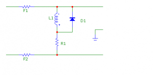
On another note, I've also noticed that the Chipamp kit has dropped the implementation of the enameled copper wound L 0.7 uH inductor/10 Ohm resistor (on LM3886 IC's pin 3 to Spkr output) as seen on the SC/Jaycar PCBs and on the "Typical Single Supply Audio Amplifier Application Circuit" on the TI LM3886 datasheet, as per the original SC design I am familiar with.
Are DIYers out there adding the wire wound resistor to the speaker outputs of their ChipAmp kits?
(I did read a lot on this here and note differences of opinion, but remain unclear as to whether or not this inductor/resistor should be implemented on the standard ChipAmp kit)
Any opinions or feedback on this would be greatly appreciated.
Cheers.
Apologies for the misplaced image, it is nonetheless, the Chipamp PCB set, showing no fuses.
Firstly, I did search the site fairly exhaustively for this issue and may well have missed it, but I did do my best. I'm new here and to it's credit, the DIY Audio site is an infinitely huge resource and a large if not a little intimidating at first...
My question is not about mains 240VAC (or 110VAC) AC inlet fuses, that has been well covered here and is not an issue for me, 240VAC 3A slo-blow always works fine on my LM3886 builds thus far.
I have a query relating to the absence of fuses on LM3886 amplifier PCBs on ChipAmp's LM 3886 kit, when compared with other SC/Jaycar type examples I have previously built.
The 1995 Silicon chip (SC), aka Altronics, aka Jaycar LM3886 amplifier boards all have clearly visible 2 X 2A fuses across rectified DC power coming from the PSU, into each of the amplifier PCBs.
An externally hosted image should be here but it was not working when we last tested it.
The ChipAmp LM3886 version does not have these fuses.
An externally hosted image should be here but it was not working when we last tested it.
I've built the Silicon chip version a couple of times, without issue. One has been in faithful service for 15 years and has never blown one of these 4 X 2A PCB mount fuses, but SC obviously put them there for a reason.
Has anyone added this fuse configuration to the Chipamp kit?
Does anyone feel that the ChipAmp LM3886 kit requires such fuses, or is their provision somehow already catered for within the somewhat revised ChipAmp design?
I've just purchased the ChipAmp LM3886 kit, am working on layout for my amp and wonder if anyone has discovered if they need this set of fuses and how they implemented them if so.
On another note, I've also noticed that the Chipamp kit has dropped the implementation of the enameled copper wound L 0.7 uH inductor/10 Ohm resistor (on LM3886 IC's pin 3 to Spkr output) as seen on the SC/Jaycar PCBs and on the "Typical Single Supply Audio Amplifier Application Circuit" on the TI LM3886 datasheet, as per the original SC design I am familiar with.
Are DIYers out there adding the wire wound resistor to the speaker outputs of their ChipAmp kits?
(I did read a lot on this here and note differences of opinion, but remain unclear as to whether or not this inductor/resistor should be implemented on the standard ChipAmp kit)
Any opinions or feedback on this would be greatly appreciated.
Cheers.
Apologies for the misplaced image, it is nonetheless, the Chipamp PCB set, showing no fuses.
An externally hosted image should be here but it was not working when we last tested it.
Last edited:
You need to be sure that the 3 amp mains fuse will blow in the event of a single diode failure within the bridge rectifier. That depends on several factors such as reservoir cap value and transformer capability. The LM3886 would almost certainly fail 'catastrophically' simply spitting itself apart. Don't assume the chip would be the only item to fail, you have to cover all posibilities for safety.
You should always add the output inductor unless the stability of the amp is proved beyond doubt into any capacitive load that may be encountered.
You should always add the output inductor unless the stability of the amp is proved beyond doubt into any capacitive load that may be encountered.
If one supply rail fuse opens due to nuisance blowing, then the output will almost certainly go to the other supply rail. This nuisance blowing will then damage your speaker, unless you have a DC detect and a fast speaker isolation system implemented.
Your T3A mains fuse will pass 750W for ever when there is a major calamity in your amplifier.
It will even pass 1500W for a long time, maybe more than a few minutes before it blows.
Look up the fuse datasheet and see what they specify for a guaranteed rupture time for twice rated current and ten times rated current.
You may get a surprise.
I always recommend a close rated mains fuse. It can reduce the fault current passing time by a factor of ten or more.
Why thank you Gents, I feel welcome!
Jon, thanks for the tip, I figured as much...
I suppose chip failure will depend on almost any fault condition, which in short, says I should use a fuse. SC put them there, but I've never seen one blow yet. Still, I don't love the smell of burning ICs in the morning...
Tromperie, thank you, I shall look up that part number for the upright fuseholder, I was either unaware, or forgot they existed.
My next logical question was going to be how one implements these fuses, as I have very little real estate on the rear of chassis for 4 extra fuseholders, nor would I wish to run leads that far, so many thanks for the tip. Also I have very little PCB real estate on the chipamp Amplifier PCBs, as you would know. I'm working in one of those small extruded aluminium enclosures with heatsink as sides and I'm sure a fuseholder solution shall present itself.
Mooly! Yes, I have been reading your posts containing some stuff on Zobel and Thiele networks. This amp may encounter short or long speaker runs, or possibly run into 4 ohms if it sees something like an Event 20/20 monitor in the future (it may be re-homed), but for now, I shall build it for my old faithful 8 ohm monitors.
I used to build satellite comms & amplifiers all day, good at assembly and procedure, but an engineer that does not make me, that's for sure. This is my 3rd LM3886 amp, my first from chipamp. The first two I built were the Altronics/SC design. Those first two amps have the wound 10 ohm resistor on the spkr out, which I understand is a low pass filter (I was a Telephone Tech back in the dark ages) and may help with tweeter cooking or the possibility of minimising/negating some amp instability into differing loads or environments. These wound resistors are a feature I would like to keep, but I also don't fully understand what chipamp is doing instead, on pin 3 spkr output with the 2.7 Ohm 2W and 0.1uF (Is this an "RF shunt to ground" cap?) capacitor (Page 3). I do build carefully for end-use-environment with a view to avoiding catastrophic failure, but don't we all?")
Transformer is a Powertran 160VA 25+25, which has given faithful but minimal service in my last LM3886 amp and is to be recycled. Caps are whatever chipamp included, Panasonic 10,000uF, if that's of any use to you. At this point, I'm not looking at any "gains" or tweaks, just to get it working and see how it sounds "as-is" from chipamp. I can rework/repair well, and add anything that needs tweaking later.
doors666, you raise a concern for me! Please do tell what will happen if one of these fuses blows. Does this point negate the use of a fused amplifier PCB?
I should look into building for the unlikely event of catastrophic transformer failure and employ the bridge rectifier based protection circuit that (I think) Rod Elliot mentions (unfamiliar with it) and that I've seen used here in a few amps...
Thanks chaps, I do appreciate the input, indeed.
Any thoughts, I'm open to suggestions.
Thanks again.
EDIT: Thanks Andrew T, did not see your post while I was writing.
I will check out lower fuse ratings indeed.
I was going with again a kit recommendation at 3A slo-blo, because of the current inrush.
But I shall check the datasheets, as I seem to recall a normal 2A fuse working quite well in one of these amps, but it has been 15 years since my last LM3886 build and the memory is foggy.
Cheers.
Jon, thanks for the tip, I figured as much...
I suppose chip failure will depend on almost any fault condition, which in short, says I should use a fuse. SC put them there, but I've never seen one blow yet. Still, I don't love the smell of burning ICs in the morning...
Tromperie, thank you, I shall look up that part number for the upright fuseholder, I was either unaware, or forgot they existed.
My next logical question was going to be how one implements these fuses, as I have very little real estate on the rear of chassis for 4 extra fuseholders, nor would I wish to run leads that far, so many thanks for the tip. Also I have very little PCB real estate on the chipamp Amplifier PCBs, as you would know. I'm working in one of those small extruded aluminium enclosures with heatsink as sides and I'm sure a fuseholder solution shall present itself.
Mooly! Yes, I have been reading your posts containing some stuff on Zobel and Thiele networks. This amp may encounter short or long speaker runs, or possibly run into 4 ohms if it sees something like an Event 20/20 monitor in the future (it may be re-homed), but for now, I shall build it for my old faithful 8 ohm monitors.
I used to build satellite comms & amplifiers all day, good at assembly and procedure, but an engineer that does not make me, that's for sure. This is my 3rd LM3886 amp, my first from chipamp. The first two I built were the Altronics/SC design. Those first two amps have the wound 10 ohm resistor on the spkr out, which I understand is a low pass filter (I was a Telephone Tech back in the dark ages) and may help with tweeter cooking or the possibility of minimising/negating some amp instability into differing loads or environments. These wound resistors are a feature I would like to keep, but I also don't fully understand what chipamp is doing instead, on pin 3 spkr output with the 2.7 Ohm 2W and 0.1uF (Is this an "RF shunt to ground" cap?) capacitor (Page 3). I do build carefully for end-use-environment with a view to avoiding catastrophic failure, but don't we all?
Transformer is a Powertran 160VA 25+25, which has given faithful but minimal service in my last LM3886 amp and is to be recycled. Caps are whatever chipamp included, Panasonic 10,000uF, if that's of any use to you. At this point, I'm not looking at any "gains" or tweaks, just to get it working and see how it sounds "as-is" from chipamp. I can rework/repair well, and add anything that needs tweaking later.
doors666, you raise a concern for me! Please do tell what will happen if one of these fuses blows. Does this point negate the use of a fused amplifier PCB?
I should look into building for the unlikely event of catastrophic transformer failure and employ the bridge rectifier based protection circuit that (I think) Rod Elliot mentions (unfamiliar with it) and that I've seen used here in a few amps...
Thanks chaps, I do appreciate the input, indeed.
Any thoughts, I'm open to suggestions.
Thanks again.
EDIT: Thanks Andrew T, did not see your post while I was writing.
I will check out lower fuse ratings indeed.
I was going with again a kit recommendation at 3A slo-blo, because of the current inrush.
But I shall check the datasheets, as I seem to recall a normal 2A fuse working quite well in one of these amps, but it has been 15 years since my last LM3886 build and the memory is foggy.
Cheers.
Last edited:
Then the close rated mains fuse should be <= VA/Vac = 160/230 = 695mAacTransformer is a Powertran 160VA 25+25
Use a T630mA, or T800mA mains fuse with a soft start circuit.
The limiting resistor could be ~120r
6 off 20r 5W, or 4 off 30r 5W, you might get away with 5 off 22r, or 3 off 39r
Thanks again Andrew.
I was just looking at a fuse datasheet (trying to dial in on the right one) and was indeed surprised, just reaching the conclusion that I would probably require something in the order of "only" 500mA, when I saw your post show up...
I don't want to bother everyone so much, so I'll try to keep questions to a minimum.
A soft start circuit? Limiting resistors?
Please excuse my ignorance here...I'm sure there are lots of ways to achieve this, that I've unwittingly owned in commercial amplifiers before.
My old 1975 Rotel RA-810 uses some type of relay at startup, but I suspect that is not what you're talking about at all... My other LM3886 amps do give quite an EMF thump from the transformer when powered up. If someone could kindly point me in the right direction (a link maybe) where there is discussion or explanation of such a soft start circuit for the LM3886, that would be appreciated and I'll not pester you any further.
In the meantime I shall research this circuit and see where I can fit it into a relatively small box, thanks Andrew T.
EDIT: Got it, I see comprehensive threads from you Andrew T, on startup and fuse issues wth LM3886.
Thanks again, and sorry for the newbie questions, I should know better... I was trained once too..
Still, that's mains fuse and I see your point Andrew, that is probably of more value to the overall design in the event of failures and that's what we're trying to protect against, I do appreciate that. I'm a safety conscious person.
I am still wondering whether or not to include fuses on the Amp PCBs or not...
If they would result in such a catastrophic fault condition, then why would SC or Altronics put them there, I wonder...
Thanks again.
Cheers.
Last edited:
test the amp for a lost supply rail.
Measure the output voltage when only PSU Zero Volts and ONE supply rail is connected.
Attach a dummy load as well. You may find that the output voltage drops very significantly when the crippled chip is asked to deliver current to the load.
Now swap to the other supply rail.
If either gives a significant output offset during this fault condition, then you must protect your speaker. Ether no rail fuses and rely on a quick rupture of the close rated mains fuse or A DC detect and speaker isolation system. BUT !!! check the DC current rating of the mechanical relay. Many are only rated for 5Adc & 30Vdc, instead of 5Aac & 250Vac.
The relay has to open reliably while the fault current is passing to the load. That could be 10Apk @ 40Vdc while the smoothing and decoupling capacitance discharge into the speaker.
I have a sneeky suspicion that a T500mA will not reliably start a 160VA transformer. The initial current pulse can be limited by the resistor, but when the relay bypasses that resistor there will be a second current pulse and this my blow the fuse.................... I would probably require something in the order of "only" 500mA, when I saw your post show up...
......................
I have some in my stock but I won't volunteer to test for you. You can blow your own fuses finding the suitable long term value.
No worries.
Thanks again Andrew.
I don't actually have a fault condition to test, as nothing has blown and I'm yet to lay an iron to the chipamp kit. I have run one of my LM3886 amps both down very low in high ambient temperatures without issue and in hot weather with absolute minimal heatsinking, and into different loads
It did take some abuse to get the "Spike" internal cutout to operate, but eventually it did. I've more or less tried to blow them up, in the course of any "normal" hostile environment they may encounter out on the road, as PAs, foldback amps, as power sections in my hybrid guitar amps, and as home Stereo amps. They are very robust ICs.
I think I spotted an LM3886 (or 2) in a Marshall head I once repaired, again foggy.
I think I shall start on lower fuse ratings and work my way up until I find a 240VAC fuse that will run the amp and of course, err on the side of caution, a procedure I've done many times. This is a simple build, I'm not looking to get into a more complex system with relays etc. My enclosure is simply not big enough. Just as long as it is electrically safe, that is my main concern.
If my previous builds are anything to go by, I triple-check everything and power up with a set of cheap speakers and (touch wood) have not had any issues.
If the chipamp kit does not top the SC version for reliability, SQ, "air" and deadly silence, I'll simply switch out the chipamp boards and go back to old faithful.
Who knows if the old National chip sounds any different to TI's production version, but I have a supply of old National T & TF ones anyway.
It's late here and the brain is ready for sleep.
Maybe I'll post pics when I'm done, if anyone ever needs to see yet another LM3886 amp...
Cheers!
Who knows if the old National chip sounds any different to TI's production version, but I have a supply of old National T & TF ones anyway.
There's absolutely no reason to believe they would. The old National products are still made using the same National processes in the same manufacturing facilities that were in place when the products were first qualified. Same process, same test program, same everything. In many cases, the same people even.
There were a few cases of overlap at the merger. The LM317 springs to mind. In some cases of overlap, the National chips won (because they were better) and are the ones you buy, though they now have a TI logo on them. In other cases, such as the LM317, at least the data sheet is the same TI data sheet as before the merger. This would imply that it's the TI version of the chip that you're buying. That's a bit unfortunate as the National version of the IC was much better characterized and the data sheet a lot better.
The spec table of the data sheet is a legally binding contract. It is a big flippin' deal to change the data sheet of a production part. Key customers need to be notified. They may have to requalify the part (huge expense for the customer, may knock your IC out of their socket), etc. Manufacturers, such as TI, don't just change the process recipe arbitrarily without telling anybody.
As for the fusing question. You definitely need a fuse on the primary side of the transformer. This is easy to do with an IEC power inlet that has the fuse holder built in. Rail fuses, on the other hand, are more likely to cause degraded sound quality. Their resistance is highly non-linear, so the voltage drop across them varies non-linearly with the output current of the amp. You'll need an amp with stellar supply rejection to be able to deal with that and still provide good performance.
Tom
Last edited:
Manufacturers, such as TI, don't just change the process recipe arbitrarily without telling anybody.
Hi Tom,
I think they came pretty close with this one
The device changed to a quasi comp output stage and yet retained the same base number.Very, very, very confusing for anyone not examining every detail of the full type number and checking the corresponding data sheets.
Post #54,
http://www.diyaudio.com/forums/anal...opamp-compensation-technique.html#post4391591
I agree Mooly,
Working in a Satellite comms production facility in the past, we had to appoint an Engineer of vast experience to our purchasing department, solely for the purpose of assessing components for fit, form and function in our critical end-use-applications. He had the unenviable task of approving for our use, $6 million in "on-site inventory" components that we used.
He was a busy man...
ICs did get knocked out of sockets, and when for example, a diode factory burns down, a manufacturer like us may find themselves down the list for resumption of supply of said component and a substitute need be sourced or our production lead times go out the window.
Data sheets acknowledged, some critical applications will require parts within even tighter performance spec than datasheets will specify, meaning that in reality, a lot of stock gets tested to our spec, for our purposes and binned from the outset.
A component may well test within the guidelines on the datasheet, but it may also fail our exacting requirements. I've lost count of the number of components over the years, that were obsoleted with almost no notice, batches that performed differently and outright junk some suppliers would send, and to a premiere manufacturer I might add.
So, appointing a very experienced senior Engineer of 50 years experience to purchasing (who would rather have been in retirement) was use of vital skill and resources that we previously had elsewhere, but a necessary step whilst principal component suppliers continue to vary their product, often without notice and without any amendments to the data sheet.
I doubt amending the data sheet will have been of any real use, on the production floor, it would have left us in the same position, perhaps "notified" that we still had to find another part or engineer around it.
In the middle of a war in 2003, producing vital sat-comms equipment, leaves little time for legalities of dataheets and engaging with semantics with suppliers, one has to get the product to behave within spec and get it out the door, with engineering done right.
This is not an argument for me to prosecute, but merely a statement of realities in production and is quite typical of daily challenges manufacturers face.
Even the DIYer, may find themselves binning half their JFETs in making a basic buffer amplifier...
Speaking of substitutes, with relevance to the LM3886 mentioned in this thread...
I have just found in my parts supply, and was about to use four LM3886T ICs.
They are all labelled as LM3886T and are all National old stock.
Three of them are prefixed with a code - JM28AC.
One of them is prefixed with a code - PM28AF.
I note that the PM28AF will not fit, exactly, where the JM28AC does, as when in-situ, the mounting screw hole alignment is different, about 0.5mm lower.
Of course an easy fix, but in some applications, this is a make or break example of how some components just don't fit where they should, or once did.
All were ordered at once, which is interesting...
The data sheets do not yield much info on this.
Anyone here know the difference between these prefix codes? (if any)
Or to put it another way;
Would anyone here run a pair of National LM3886T ICs, each labelled JM28AC and PM28AF respectively, in your amplifier, and call them a "matched" pair?
Cheers.
Absence of positive rail is usually not an issue for these chips. Absence of negative rail will latch chip to +50% of Vcc.
A very handy solution is to run a simple output series relay, with the coil powered by the two rails after the fuse. Absence of any one rail will simply shut the relay off till the fuse is replaced. The relay coil needs a balancing diode, and a series resistor will be required to drop the voltage across the coil down to the required operating level, by a simple Ohm's Law calculation.
A very handy solution is to run a simple output series relay, with the coil powered by the two rails after the fuse. Absence of any one rail will simply shut the relay off till the fuse is replaced. The relay coil needs a balancing diode, and a series resistor will be required to drop the voltage across the coil down to the required operating level, by a simple Ohm's Law calculation.
Hi to all,
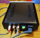
Returning with build nearing completion.
The chipamp non-inverting stereo kit is housed and delivering sound.
Thanks to Andrew T for the advice on mains fusing, after blowing a slo-blow 680mA mains fuse I was able to settle on slo-blow 800mA fuse for AC mains duties.
It seems to cope with startups, frequent on/off switching, inrush current and transients in the AC mains supply itself. I have provided the new owner (this is a freebie or a friend who needs an amp) with 1A slo-blow fuses if the 800mA proves to be a nuisance. I have not implemented any fuses on the amplifier PCBs.
Couple of issues I had with Chipamp's "assembly instructions" in the absence of the BrianBellGT website, which must have been offline for some time now. Still, plenty of info on the net about these amps.
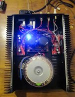
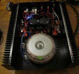
At first I completed the kits as pictured below.
Since the pictures were taken, I added the 10 Ohm resistor wound with the 0.7 uH inductor on the +ve spkr outs as shown on the LM3886 datasheet. The amp has been re-homed, where is has picked up some 50hZ noise, probably a result of my grounding method, which was to follow Chipamp's instructions.
I realised after I sent it, that I had only tested the amp when interacting with double insulated 2 pin AC mains equipment, all of which had no mains Earth and hence, no way to make an external ground loop (a CD player and small Soundcraft mixing desk were used as a source for testing). So, I missed the opportunity to see how it behaved/interacted in it's new home with the mains and signal sources offered to it.
It is coming back to me for some work to quieten it up.
I would like to implement DC blocking capacitors, as the signal source is unknown to me. This forum would indicate that deploying DC blocking capacitors on the inputs of this amp is simply good practice and something I omitted as I assumed the source, a professional mixing console, would be free of DC on it's own signal outputs. It may well be, but I don't have the luxury of testing the mixing console, so I must assume the amp may see DC coming in, and duly block it.
A few questions on DC blocking capacitors...
What value for a chipamp Gainclone kit? uF Volts ratings, anyone?
I've seen quite a few different ideas here, but 1uF seems common from what I can find on the site.
Would these from my local store be suitable as DC blocking caps on the LM3886 amplifier?
This is a real noob question, but I can't seem to find out how the DC blocking caps are wired into the amp...
How does one wire them to the inputs?
"across" +ve to -ve on each channel, or one cap each on the +ve signal in?
Do I need them on the signal ground too, as in, do I need 4 x of them to block DC coming into the amp?
I would be very happy to see others DC blocking caps and how they're implemented.
I know that DC caps alone will probably not help the hum this amp has picked up. I am pretty sure that Chipamp's stock ground return layout is not a straightforward star ground. I've seen Andrew T's posts on keeping signal grounds and mains grounds separate (apologies for wording there...) and went with that idea as did Chipamp it seems. But on my previous non-Chipamp builds, if I ran an Earth Buss Bar and ran the ground returns for the amplifiers, PSU and spkr -ves all back to this one earth point, it killed all hum.
Mike from Liquid Audio has a great example of this kind of earth wiring modification I think I need to do. Scroll to the last 4 of Mike's pics for before and after ground wiring from Mike on the LM3886 chipamp kit. Mike has shifted from Chipamp's grounding layout:
Before:
http://i1.wp.com/liquidaudio.com.au/wp-content/uploads/2014/10/DSC6266.jpg
To his own star config, on which Mike had this to say:
http://i1.wp.com/liquidaudio.com.au...81986746-764x1024.jpg?zoom=1.5&resize=630,845
This is what I think I may need to do...
Add DC blocking caps of the correct value and correct wiring, as I'm unsure how this is done.
Change the grounding to the scheme Mike has implemented, returning loudspeaker, amplifier and PSU grounds to a Buss Bar and to the chassis earth and then to mains Earth.
If anyone could chime in on an adequate DC blocking cap and wiring for it, that would be great.
I sort of understand what Andrew T has said about keeping signal and mains grounds separate, but maybe I don't understand it... Apologies AndrewT, a lot of what you post goes over my amateur DIYer's head.
If there's a problem with returning the loudspeaker, amplifier and PSU grounds all to the same point, could someone explain the issues with that?
It's a lot of questions, but I've searched the site for weeks and can't seem to find anything (indexed) that outlines these things, although I am sure it has been covered many times. Sorry about that, weeks of site searches are offering me diminishing returns! So, I have to ask...
Thanking you all in advance.
Cheers.
Returning with build nearing completion.
The chipamp non-inverting stereo kit is housed and delivering sound.
Thanks to Andrew T for the advice on mains fusing, after blowing a slo-blow 680mA mains fuse I was able to settle on slo-blow 800mA fuse for AC mains duties.
It seems to cope with startups, frequent on/off switching, inrush current and transients in the AC mains supply itself. I have provided the new owner (this is a freebie or a friend who needs an amp) with 1A slo-blow fuses if the 800mA proves to be a nuisance. I have not implemented any fuses on the amplifier PCBs.
Couple of issues I had with Chipamp's "assembly instructions" in the absence of the BrianBellGT website, which must have been offline for some time now. Still, plenty of info on the net about these amps.
At first I completed the kits as pictured below.
Since the pictures were taken, I added the 10 Ohm resistor wound with the 0.7 uH inductor on the +ve spkr outs as shown on the LM3886 datasheet. The amp has been re-homed, where is has picked up some 50hZ noise, probably a result of my grounding method, which was to follow Chipamp's instructions.
I realised after I sent it, that I had only tested the amp when interacting with double insulated 2 pin AC mains equipment, all of which had no mains Earth and hence, no way to make an external ground loop (a CD player and small Soundcraft mixing desk were used as a source for testing). So, I missed the opportunity to see how it behaved/interacted in it's new home with the mains and signal sources offered to it.
It is coming back to me for some work to quieten it up.
I would like to implement DC blocking capacitors, as the signal source is unknown to me. This forum would indicate that deploying DC blocking capacitors on the inputs of this amp is simply good practice and something I omitted as I assumed the source, a professional mixing console, would be free of DC on it's own signal outputs. It may well be, but I don't have the luxury of testing the mixing console, so I must assume the amp may see DC coming in, and duly block it.
A few questions on DC blocking capacitors...
What value for a chipamp Gainclone kit? uF Volts ratings, anyone?
I've seen quite a few different ideas here, but 1uF seems common from what I can find on the site.
Would these from my local store be suitable as DC blocking caps on the LM3886 amplifier?
This is a real noob question, but I can't seem to find out how the DC blocking caps are wired into the amp...
How does one wire them to the inputs?
"across" +ve to -ve on each channel, or one cap each on the +ve signal in?
Do I need them on the signal ground too, as in, do I need 4 x of them to block DC coming into the amp?
I would be very happy to see others DC blocking caps and how they're implemented.
I know that DC caps alone will probably not help the hum this amp has picked up. I am pretty sure that Chipamp's stock ground return layout is not a straightforward star ground. I've seen Andrew T's posts on keeping signal grounds and mains grounds separate (apologies for wording there...) and went with that idea as did Chipamp it seems. But on my previous non-Chipamp builds, if I ran an Earth Buss Bar and ran the ground returns for the amplifiers, PSU and spkr -ves all back to this one earth point, it killed all hum.
Mike from Liquid Audio has a great example of this kind of earth wiring modification I think I need to do. Scroll to the last 4 of Mike's pics for before and after ground wiring from Mike on the LM3886 chipamp kit. Mike has shifted from Chipamp's grounding layout:
Before:
http://i1.wp.com/liquidaudio.com.au/wp-content/uploads/2014/10/DSC6266.jpg
To his own star config, on which Mike had this to say:
After:"One small issue I had and this came about by just not really think carefully enough about the wiring layout, was that I experienced some hum on initial testing. After thinking and reading, I decided to modify the ground wiring layout, as shown in the images below. I basically rewired the ground wiring to include a true star ground, and to avoid the multiple earth returns of my initial layout.
Look below, to the rear of the chassis near the inputs – you will see I’ve implemented a thick buss bar, linking loudspeaker grounds, amplifier and power supply grounds to one central point, which then leads out to the chassis ground, at which point the mains ground is connected. This arrangement is now totally silent."
http://i1.wp.com/liquidaudio.com.au...81986746-764x1024.jpg?zoom=1.5&resize=630,845
This is what I think I may need to do...
Add DC blocking caps of the correct value and correct wiring, as I'm unsure how this is done.
Change the grounding to the scheme Mike has implemented, returning loudspeaker, amplifier and PSU grounds to a Buss Bar and to the chassis earth and then to mains Earth.
If anyone could chime in on an adequate DC blocking cap and wiring for it, that would be great.
I sort of understand what Andrew T has said about keeping signal and mains grounds separate, but maybe I don't understand it... Apologies AndrewT, a lot of what you post goes over my amateur DIYer's head.
If there's a problem with returning the loudspeaker, amplifier and PSU grounds all to the same point, could someone explain the issues with that?
It's a lot of questions, but I've searched the site for weeks and can't seem to find anything (indexed) that outlines these things, although I am sure it has been covered many times. Sorry about that, weeks of site searches are offering me diminishing returns! So, I have to ask...
Thanking you all in advance.
Cheers.
Attachments
Last edited:
DC blocking capacitors are there to block DC passing from the Source to the Receiver.
They also define the High Pass Filter frequency of the passive filter at the input to the Receiver and they also prevent a volume control interacting with the input current of the Receiver.
If the Receiver has an input impedance of ~100kohms, then a 1uF will pass all the audio signal.
They get wired into the "hot" or signal line into the Receiver.
But you must add a grounding resistor before the cap and ensure there is a grounding resistor after the cap. This last one should already be fitted on the receiver PCB.
Wire a 1M0 or 2M2 ¼W resistor between Hot and Cold (Signal Flow and Signal Return or RCA pin and RCA barrel).
Wire the 1uF into the lead from RCA pin to Receiver hot/signal input pad.
You have not mentioned RF interference, so I'll recommend you fit a 47pF NPO ceramic across the RCA input socket (Hot to Cold). This is effectively in parallel to that 1M0.
Last edited:
- Status
- This old topic is closed. If you want to reopen this topic, contact a moderator using the "Report Post" button.
- Home
- Amplifiers
- Chip Amps
- ChipAmp LM3886 amplifier PCBs - to fuse or not to fuse?