wirewiggler said:.....always good someone else is looking out for my health and welfare.
Bill
That's called the government...


davidhugo said:RE:Another idea is to sacrifice a cheap donor pot. Open it up and
discard the shaft and other parts and just use the front mounting hardware.
Nice to see some lateral thinking -it works- sheer genius. Thanks.
dh
I have to agree. A small sacrifice for a HUGE gain...
Jolly good thinking!
davidhugo said:Nice to see some lateral thinking -it works- sheer genius. Thanks.
dh
Glad to know that worked. Do post a pic.
I'll try out my own idea soon for a MyRef amp I completed last weekend. ;-)
Another thing I found is that the brass insert from a 60 amp electrical
connector strip makes an excellent 6mm shaft coupler. Cheap
and easy to get anywhere!
http://www.reuk.co.uk/buy-60A-JUNCTION-BLOCK.htm
http://www.luxurylighting.co.uk/60-amp-connector-strip-2335-p.asp
Prasad
Here in the US we have Home Depots and Lowes which are home improvement stores. I get some plastic spacer tubes for large screws / bolts and I use that for my shaft couplers as they are not conductive and isolate the shaft from the pot. Magnetic fields and static electricity are isolated from the pot itself.
But I always had the issue of the bushing in the front panel until quadtech posted that excellent idea.
But I always had the issue of the bushing in the front panel until quadtech posted that excellent idea.
" ... Another thing I found is that the brass insert from a 60 amp electrical
connector strip makes an excellent 6mm shaft coupler. Cheap
and easy to get anywhere! ..."
In Northern California, the Halted.com folks have lots of these for ~ US$1 each, for gangs of six to eight pairs. Surplus stock, but unused as far as I can tell. ( http://www.halted.com/commerce/catalog/srhkeyword.cz;jsessionid=D73D6706BE91DF3F98ACC39330A1A2A6 )
connector strip makes an excellent 6mm shaft coupler. Cheap
and easy to get anywhere! ..."
In Northern California, the Halted.com folks have lots of these for ~ US$1 each, for gangs of six to eight pairs. Surplus stock, but unused as far as I can tell.
( http://www.halted.com/commerce/catalog/srhkeyword.cz;jsessionid=D73D6706BE91DF3F98ACC39330A1A2A6 )An externally hosted image should be here but it was not working when we last tested it.
An externally hosted image should be here but it was not working when we last tested it.
5 channel LM3875 driving into 5 4ohm speakers, plus a 200 watt discrete block that drives the sub.
No input caps at all, film caps directly across the rails.
25-+ volt rails for the LM chips, and -+55 volts for the sub amp.
yea, very on the heavy side.
Also finished the controller for it, which is a timer based circuit that controls soft turn on, dethump, etc etc.
I have more pics of it if anyone is interested.
Also finished the controller for it, which is a timer based circuit that controls soft turn on, dethump, etc etc.
An externally hosted image should be here but it was not working when we last tested it.
I have more pics of it if anyone is interested.
Rainwulf said:In this thread will be ok?
Why not? That is the purpose of it, right?
I for one would like to see more pictures of Rainwulf's project.
An externally hosted image should be here but it was not working when we last tested it.
An externally hosted image should be here but it was not working when we last tested it.
An externally hosted image should be here but it was not working when we last tested it.
I have yet to put on snubbers. I have to get more MKT caps and the matching resistors, though at this point i dont know if i will worry.
An externally hosted image should be here but it was not working when we last tested it.
An externally hosted image should be here but it was not working when we last tested it.
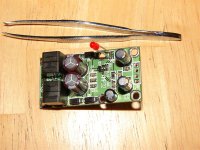
The assembly the rotates 3 alps pots at the same time. Its to set the max level of the amp.
An externally hosted image should be here but it was not working when we last tested it.
An externally hosted image should be here but it was not working when we last tested it.
An externally hosted image should be here but it was not working when we last tested it.
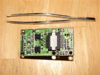
LM3875 module with decoupler across the power pins.
The amps are also DC coupled. no Cin.
An externally hosted image should be here but it was not working when we last tested it.
An externally hosted image should be here but it was not working when we last tested it.
An externally hosted image should be here but it was not working when we last tested it.
An externally hosted image should be here but it was not working when we last tested it.
Temperature controller fans. Run very slow until the amp heats up a bit, which means loud music is playing, so you wont hear the fans anyway.
I dont have pics of it yet, but i have installed speaker cut of relays that stop any thumping on turn on, i have installed an earth loop breaker, and also a turn on surge limiter, as well as a slave circuit, so the amp is only on when the computer is on.
I can draw a circuit diagram of all that too if anyone wants. Very simple circuits.
More pics of it progress here. Big though.
An externally hosted image should be here but it was not working when we last tested it.
Thats the sub amp, obviously not a chip amp.
I even made my own speakers.
An externally hosted image should be here but it was not working when we last tested it.
An externally hosted image should be here but it was not working when we last tested it.
- Home
- Amplifiers
- Chip Amps
- Chip Amp Photo Gallery