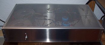
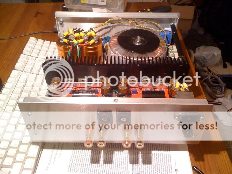
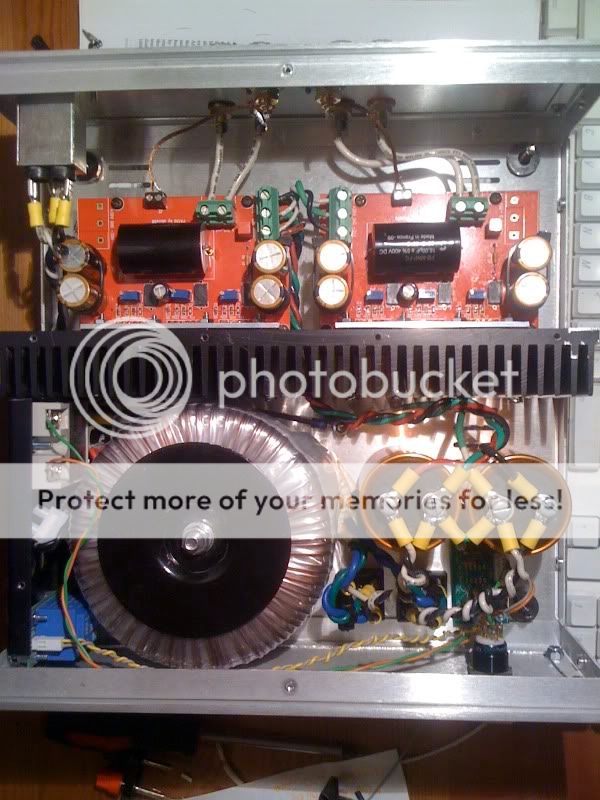
Some more pix... Just brief Description, This is a regulated version gainclone with a supply of around +-28v, I used Peter Daniel's pcb's, with the Zobel network connected and ci used. Its connected to a DIY speaker as well, a backloaded horn using Fostex FE126en. This is my first DIY projects and I'm loving it...The sound? well.. its fantastic!!
Did you paint the capacitors orange?
And it looks very cool.
I see many exposed conductive parts.
How have you connected them to the Safety Earth, when there is no enclosing metal chassis?
Hi AndrewT,
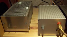
Those pcb's with orange caps on are not connected, it's for a second project 'GC monoblocks' you can see the amp more with full description here Project | Homebuilt Hi-Fi - A user submitted image showcase of high quality home built hi-fi components.
Did you paint the capacitors orange?
And it looks very cool.
Thanks troystg, yup! I painted it...
I see many exposed conductive parts.
How have you connected them to the Safety Earth, when there is no enclosing metal chassis?
The psu box has a metal base that is connected to earth, Unit is protected with a line fuse in series with the mains that I hope would open in case of a short.
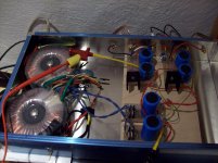
Now they should add some coloration to the sound for sure.Thanks troystg, yup! I painted it...
Hi,Hi,
all three pics use a total of <400kB and still look detailed.
Well done in both the photography and the build.
Thanks.
these pcb were build on the basis from MickF his minimal chip amplifier. PSU derive from Carlos Machado (a countryman) his snubber.
well, now I'm trying the little Tripaths, but this is the wrong forum here...
")
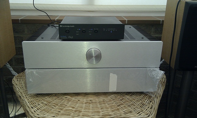
Nice work. Where did you buy the heatsinks?Hi all, my Peter Daniel LM3875 amp.
Copper hood
Aluminum front and back plates and base
Copper feet
my first project
Here is my first diy amplifier, a PA150 using the unbridged version of alexw88 BPA300 design, 3 parallel lm3886's per channel. Everything is enclosed in a parmetal case.
Very, very pleased with it so far. Can't wait to hear it with some future components; buffalo II dac, ivy III pre and a pair of usher 2.5's
At last, it's complete:
Better than I had hoped. It's got a great amount of power. The highs, mids are very crisp and detailed- which is a natural lm3886 characteristic as far as i know. The large capacitors supply lots bottom end, I can crank it to 11 and everything is still very clean, undistorted and punchy. I plan on replacing my speakers in the next few months to something of higher caliper; with better bass response to match this amplifier. I also plan on partnering my amplifier with something better than a macbook + aliendac -onboard volume control . (buffalo II/Ivy up next )
Construction took much longer than anticipated, especially when I don't have the proper tools (ie large drill bits). I'm really surprised how much I've learned in one project, I just wish i could be feverishly hooked to my calculus/physics courses like i can to diy-audio.
This amplifier does run a little hot, at high volumes almost too hot to touch. (not sure how much heat these chips can handle or if my heatsink is quite large enough) For the most part i'll keep the volume at moderate levels. I'm surprised peranders advised against the unbridged design (as in they these boards weren't designed for it) but this is definitely a worthy build and I'm very happy so far. I can't really fathom the BPA300's power or when it would ever be needed.
. (buffalo II/Ivy up next )Construction took much longer than anticipated, especially when I don't have the proper tools (ie large drill bits). I'm really surprised how much I've learned in one project, I just wish i could be feverishly hooked to my calculus/physics courses like i can to diy-audio.
This amplifier does run a little hot, at high volumes almost too hot to touch. (not sure how much heat these chips can handle or if my heatsink is quite large enough) For the most part i'll keep the volume at moderate levels. I'm surprised peranders advised against the unbridged design (as in they these boards weren't designed for it) but this is definitely a worthy build and I'm very happy so far. I can't really fathom the BPA300's power or when it would ever be needed.

You're absolutely right ted, given my listening restrictions of a 12x10 ft bedroom I think the bpa300 would be too much. Once i'm out of a bedroom and have greater than a part-time waiter/student income I'll definitely step up. Until then i'll just have to try and stay within my means .
Beautiful setup by the way! Clean and sleek. How are you enjoying your amplifier?
.Beautiful setup by the way! Clean and sleek. How are you enjoying your amplifier?
its sounding very good. More or less as you have described. I have slight issue with the optical volumn control but i'm enjoying it to the point i dont want to take it out of use to fix
This is true. I would have prefered not to use zip ties to mount them but they do the job ok.
only hard to fix them (mounting bracket not included) - i using DIY U shape bracket from aluminium.
This is true. I would have prefered not to use zip ties to mount them but they do the job ok.
Last edited:
My creation
Here's my creation.
LM1875 stereo amp based on Rod Elliot's circuits. Designed and made my own PSU PCB and amplifier PCB. The amplifier PCB was done on a CNC router and is double sided whilst the power supply board was made using the UV method. No special components around just fairly bog standard parts from my supplier. The only expensive parts to note are the ALPS RK27 series pot and the massively over-rated Finder relay which is used so that i could use a smaller front panel switch. The case is a 3U (again oversized) rack case from Hi-fi2000 and the knob (which matches incredibly well) is surprisingly from Maplin.
I haven't done much in the way of measurements on the amp yet (partly because I don't have a dummy load) but it certainly sounds good. With the volume all the way up barely any hiss or hum can be heard, even with your ear close to the speaker (the speakers are quite inefficient though).
Front panel (4mm aluminium)
Rear panel with in/out connectors, filtered IEC inlet and mains fuse.
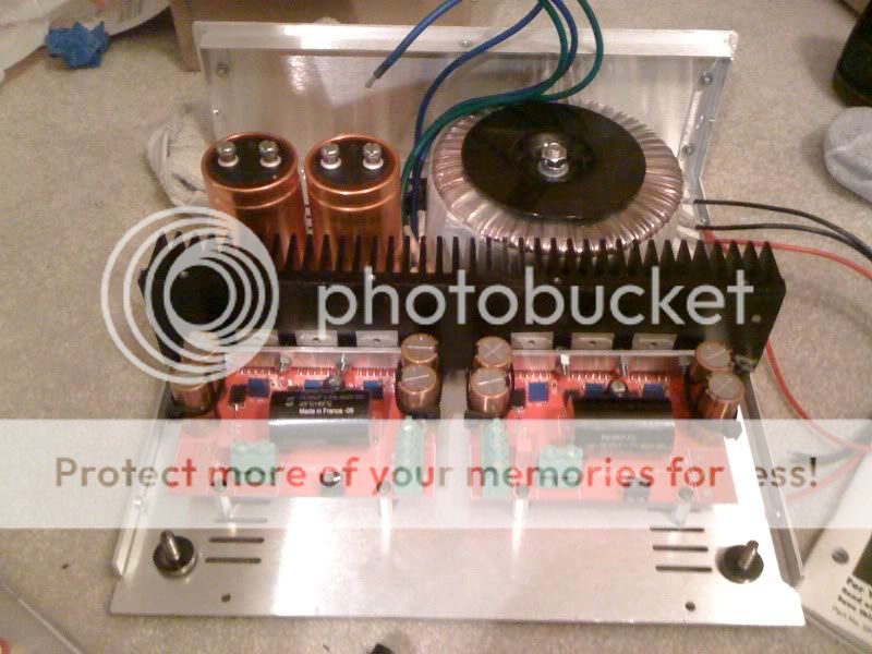
Overall internal view. The glue on the top of the capacitors is to attempt to dampen any vibrations. There is plenty of space left in there though...
Amplifier PCB and PS capacitors (10,000uF x2 per rail). These have enough storage that the power LED stays on for about 20-30 seconds.
Finally, the mains transformer and the relay. The transformer is a 160VA 16+16V type and gives around 22V after rectification and filtering.
Here's my creation.
LM1875 stereo amp based on Rod Elliot's circuits. Designed and made my own PSU PCB and amplifier PCB. The amplifier PCB was done on a CNC router and is double sided whilst the power supply board was made using the UV method. No special components around just fairly bog standard parts from my supplier. The only expensive parts to note are the ALPS RK27 series pot and the massively over-rated Finder relay which is used so that i could use a smaller front panel switch. The case is a 3U (again oversized) rack case from Hi-fi2000 and the knob (which matches incredibly well) is surprisingly from Maplin.
I haven't done much in the way of measurements on the amp yet (partly because I don't have a dummy load) but it certainly sounds good. With the volume all the way up barely any hiss or hum can be heard, even with your ear close to the speaker (the speakers are quite inefficient though).
Front panel (4mm aluminium)
An externally hosted image should be here but it was not working when we last tested it.
Rear panel with in/out connectors, filtered IEC inlet and mains fuse.
An externally hosted image should be here but it was not working when we last tested it.
Overall internal view. The glue on the top of the capacitors is to attempt to dampen any vibrations. There is plenty of space left in there though...
An externally hosted image should be here but it was not working when we last tested it.
Amplifier PCB and PS capacitors (10,000uF x2 per rail). These have enough storage that the power LED stays on for about 20-30 seconds.
An externally hosted image should be here but it was not working when we last tested it.
Finally, the mains transformer and the relay. The transformer is a 160VA 16+16V type and gives around 22V after rectification and filtering.
An externally hosted image should be here but it was not working when we last tested it.
Mabe you don't have a bleeder resistor for the psu?Amplifier PCB and PS capacitors (10,000uF x2 per rail). These have enough storage that the power LED stays on for about 20-30 seconds.
Nice built!
My second amplifier had 3*6800uF per supply rail.Mabe you don't have a bleeder resistor for the psu?
Nice built!
It reproduced undistorted music for about 2minutes after unplugging from the mains. Then turned itself off silently.
Why do I need a bleeder?
- Home
- Amplifiers
- Chip Amps
- Chip Amp Photo Gallery