I keep the 303s for my ESL57s too")
My friend the ESL57 fanatic (trilple Quads) much preferred the Quad II (6 of them) and is now using a trio of the EL84 PP (cleaned up & modernized).
dave
Any more than 1500uF, it wouldn't be a GainClone, just another Chipamp. Check out the original GainCard. 6moons audio reviews: 47 Laboratory Model 4706 GainCard
Perhaps, but that doesn't mean going with more capacitance wouldn't be helpful. Freebee...I didn't compare lower PS capacitance with my 20-40kuF per channel (can't remember what I used for my LM3886) but it's definitely worth a test. I know some here think 1500/lower uF can be better than higher, but I suspect that has to do with overall impedance in the PS rather than the capacitance per se. And that's why I specifically mentioned low ESR caps.
Can you post a better image of the PCB layout?There is even room on the PSU board to add 2 capacitors.
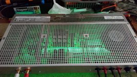
hi guys! my 1st ever chip amp. mated with a passive preamp which used to be a input selector switch.
An externally hosted image should be here but it was not working when we last tested it.
An externally hosted image should be here but it was not working when we last tested it.
An externally hosted image should be here but it was not working when we last tested it.
An externally hosted image should be here but it was not working when we last tested it.
An externally hosted image should be here but it was not working when we last tested it.
An externally hosted image should be here but it was not working when we last tested it.
Member
Joined 2009
Paid Member
hi guys! my 1st ever chip amp. mated with a passive preamp which used to be a input selector switch.
An externally hosted image should be here but it was not working when we last tested it.
how does the heatsink experience airflow?
how does the heatsink experience airflow?
i remove the glass everytime i use it ahaha planning to bore some holes to the glass. i already have drilled 4 one inch holes at the bottom. this is still a work on progress. later today im gonna install zobel circuit.
Last edited:
im also considering just a single 1 inch hole on the glass and then put a 1 inch exhaust to it. but i dont like the idea of adding a fan on any amp except for pro purposes so i might stick with boring 3 or 4 one inch holes at the glass or just remove it everytime i use the amp.
Simple LM4780 amplifier
Hi
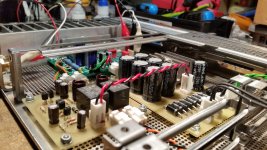
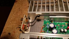
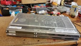
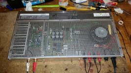
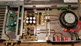
Just finished this little amp. Well, kinda finished, it still needs some deburing around all those holes in cover, and some flat front panel to hide those ugly holes in the front.
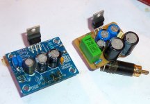
Talking about technical side, its very basic amp. I used KM TECH pcb from ebay, which is not perfect, but very close to datasheet, which is star grounded layout. Maybe sometime, I will make my own with improvements.
Parts used are mostly standard application stuff, except power supply caps. I used 1uF ceramics in place of "normal" 100 nF, and 22 uF instead of 10 uF. And ditched the 2.7 ohm resistor between signal and power grounds, because I don't see how it can do something good, if thinking based on feedback and ground routing suggestions, presented by forum member tomchr, it only can make things worse.
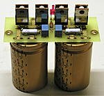
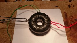
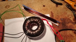
Amp has DC protection, since I had it laying around from unfinished project and because it has thiele network. Power supply PCB is from same project and has 12V regulator. Transformer is 2x17 VAC, 100VA.
DC protection need 12VDC, so I added 12.6V winding.
Before someone asks about safety earth, there isn't one in my apartment, so adding it to the projects is useless.
Hi
Just finished this little amp. Well, kinda finished, it still needs some deburing around all those holes in cover, and some flat front panel to hide those ugly holes in the front.
Talking about technical side, its very basic amp. I used KM TECH pcb from ebay, which is not perfect, but very close to datasheet, which is star grounded layout. Maybe sometime, I will make my own with improvements.
Parts used are mostly standard application stuff, except power supply caps. I used 1uF ceramics in place of "normal" 100 nF, and 22 uF instead of 10 uF. And ditched the 2.7 ohm resistor between signal and power grounds, because I don't see how it can do something good, if thinking based on feedback and ground routing suggestions, presented by forum member tomchr, it only can make things worse.
Amp has DC protection, since I had it laying around from unfinished project and because it has thiele network. Power supply PCB is from same project and has 12V regulator. Transformer is 2x17 VAC, 100VA.
DC protection need 12VDC, so I added 12.6V winding.
Before someone asks about safety earth, there isn't one in my apartment, so adding it to the projects is useless.
Attachments
-
 20190606_212828.jpg262.2 KB · Views: 289
 -
 20190606_211250.jpg346.2 KB · Views: 458
 -
 20190611_184732.jpg329.1 KB · Views: 1,135
 -
 20190611_214342.jpg392.2 KB · Views: 1,154
 -
 20190612_151430.jpg448.4 KB · Views: 1,156
 -
 01.jpg635.5 KB · Views: 1,199
 -
 64324120_1037121026677498_4741600549974048768_n.jpg139.4 KB · Views: 1,234
 -
 20190612_154624.jpg581.7 KB · Views: 618
Pasolink AmpHi
Just finished this little amp. Well, kinda finished, it still needs some deburing around all those holes in cover, and some flat front panel to hide those ugly holes in the front.
Talking about technical side, its very basic amp. I used KM TECH pcb from ebay, which is not perfect, but very close to datasheet, which is star grounded layout. Maybe sometime, I will make my own with improvements.
Parts used are mostly standard application stuff, except power supply caps. I used 1uF ceramics in place of "normal" 100 nF, and 22 uF instead of 10 uF. And ditched the 2.7 ohm resistor between signal and power grounds, because I don't see how it can do something good, if thinking based on feedback and ground routing suggestions, presented by forum member tomchr, it only can make things worse.
Amp has DC protection, since I had it laying around from unfinished project and because it has thiele network. Power supply PCB is from same project and has 12V regulator. Transformer is 2x17 VAC, 100VA.
DC protection need 12VDC, so I added 12.6V winding.
Before someone asks about safety earth, there isn't one in my apartment, so adding it to the projects is useless.
Thanks, I didn't know what was inside those cases. I bought them empty from local electronics shop for cheap.Pasolink Amp
- Home
- Amplifiers
- Chip Amps
- Chip Amp Photo Gallery