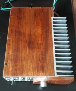
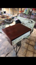
In the summer the heatsink was getting kind of… hot (43 C) so I’ve modified the case.
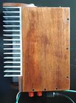
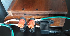
Here you have the same bottom case and internal circuit, now with a much bigger heatsink and cover.
We’ll wait for the summer to see the difference (Hot room around 30 C).
Regards
Here you have the same bottom case and internal circuit, now with a much bigger heatsink and cover.
We’ll wait for the summer to see the difference (Hot room around 30 C).
Regards
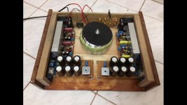
I just built for a friend a small little amp (LM3886 based).
Attachments
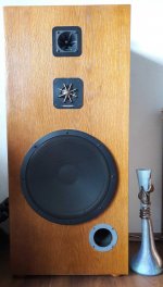
And the speakers driven by the amp... bass reflex units with 15" woofer, mid and original Motorola piezo tweeter (before they stopped the fabrication).
In the summer the heatsink was getting kind of… hot (43 C) so I’ve modified the case.
Here you have the same bottom case and internal circuit, now with a much bigger heatsink and cover.
We’ll wait for the summer to see the difference (Hot room around 30 C).
Regards
Attachments
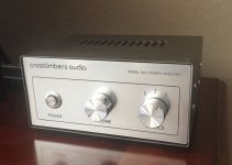
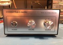
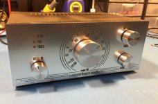
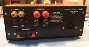
TDA7297 Amplifier
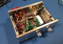
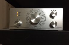
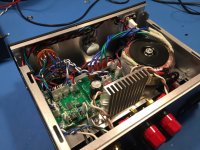
After reading positive things about the TDA7297 I decided to build an amplifier around one. The PCB is my own design. I want to clean up the internal wiring a bit but otherwise it's done, and works well.
After reading positive things about the TDA7297 I decided to build an amplifier around one. The PCB is my own design. I want to clean up the internal wiring a bit but otherwise it's done, and works well.
Attachments
After reading positive things about the TDA7297 I decided to build an amplifier around one. The PCB is my own design. I want to clean up the internal wiring a bit but otherwise it's done, and works well.
Very nice work.
Did you do the silk screen text and layout yourself or did you have to send it off to a company to have your Chassis silk screened?
I am trying to do a similar project and want the text labeling to look professional like how you did.
Did you do the silk screen text and layout yourself or did you have to send it off to a company to have your Chassis silk screened?
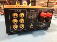
The front and back panels are laser cut/engraved 1.5mm thick acrylic done at pololu.com. The artwork(s) for the panels were created in Inkscape. The panels are held in place by the controls on the front and the connectors on the back. My immediate supervisor (wife) doesn't like to see fasteners on the front of any of the equipment I place into service in the living room. I got an exemption for the screws on the sides holding the covers on.
The cabinet is from circuitspecialists.com. It's their EM-01 model.
After 2 weeks working & blowing 2 chips. Here is my first amp and still under construction, 4.0 channel 3886 for my 5.1 project
Homebrew pcb, the layout got from various sites, any advice welcome
Homebrew pcb, the layout got from various sites, any advice welcome
Attachments
There is a discussion thread for the amp BPS is constructing, and where any comments would be welcome:
http://www.diyaudio.com/forums/chip-amps/303920-my-first-amp-its-blown-need-help.html#post5001243
http://www.diyaudio.com/forums/chip-amps/303920-my-first-amp-its-blown-need-help.html#post5001243
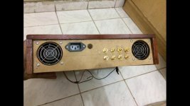
Hi BPS. Are the fans sucking in or blowing out? Where will the air entry/exit be?
These 2 fans sucking air, will make some exit hole at bottom plate (will install extra small blowing fan if necessary, the wooden case is the top case, all parts will placed upside down except the transformer will placed at bottom(due to its weight)
Last edited:
TDA7266 / Si4831 Stereo Receiver
This is a little stereo receiver I put together using a TDA7266 and a Si4831 mechanically tuned AM/FM stereo IC from Silicon Labs. Originally I wasn't happy with the way it was turning out and had set it aside. Last night I saw it languishing on a shelf so I took pity on it, put it on the bench and finished it.
This is a little stereo receiver I put together using a TDA7266 and a Si4831 mechanically tuned AM/FM stereo IC from Silicon Labs. Originally I wasn't happy with the way it was turning out and had set it aside. Last night I saw it languishing on a shelf so I took pity on it, put it on the bench and finished it.
Attachments
I would be very happy with the way it turned out if I had built that.
Thanks John. Originally I believed that the transformer was too close to the amp PCB and that there are too many wires criss-crossing the cabinet. At one point I had put it aside thinking it needed a larger cabinet and a better internal layout. Considering that it is now my office music source, it appears I was being too critical.
Member
Joined 2009
Paid Member
I wanted to ask the same questions.
But folk complain about me being too negative.
It's how you ask....
Option 1: wow, you poor sod, that thing looks like a train wreck. There's no decent air flow from looking at those photos. I'd keep an extinguisher handy or have the kid that built it ask his dad to help out a bit. (Just kidding!)
Option 2: now that's the DIY spirit with a home made wood chassis and all with the heat sinks hidden inside to preserve the good looks. Not sure how hard you plan to push those amps, will you be drawing air through some ventilation holes somewhere to flow over the heat sink fins ?
Last edited:
TDA 7375 - chip amp made of junkyard parts
Howdy folks!
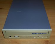
So I have desired for some time to build a chip amp for low power application and after a couple of misfortuned attemts I finally stumbled upon a chip that actually works and does that better than expected. This used to be a DVB-T receiver and a recorder, had a HDD in it, so I was lucky to have found it. The chip and Alps pot was salvaged from a Blaupunkt cassete player. The power supply is equiped with typical voltages you'd find in computers so it was that much easier.Took the wires out through a screw-on fuse holder to power the cd rom player. Yellowed plastics doesn't look appealing but I'll try to get my hands on some chemicals to clean it up. Btw, does anyone know of a product that would succesfully whiten it to original color? Tried googling but the hydrogen peroxide doesn't sound reassuring. I know professionals have got some sort of a solution for that. Next project is loudspeakers and I have some Aiwa mini component system units on a shelf, a 4" bassmid and a 2" cone tweeter. That will be finished by this summer, hopefully. Thank you in advance!
Howdy folks!
So I have desired for some time to build a chip amp for low power application and after a couple of misfortuned attemts I finally stumbled upon a chip that actually works and does that better than expected. This used to be a DVB-T receiver and a recorder, had a HDD in it, so I was lucky to have found it. The chip and Alps pot was salvaged from a Blaupunkt cassete player. The power supply is equiped with typical voltages you'd find in computers so it was that much easier.Took the wires out through a screw-on fuse holder to power the cd rom player. Yellowed plastics doesn't look appealing but I'll try to get my hands on some chemicals to clean it up. Btw, does anyone know of a product that would succesfully whiten it to original color? Tried googling but the hydrogen peroxide doesn't sound reassuring. I know professionals have got some sort of a solution for that. Next project is loudspeakers and I have some Aiwa mini component system units on a shelf, a 4" bassmid and a 2" cone tweeter. That will be finished by this summer, hopefully. Thank you in advance!
Attachments
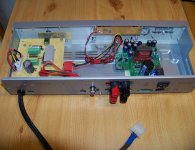
This apparatus wasn't modified in the sense that the safety earth is disconnected now. It never had that originally. The chassis is exactly as it left the factory and the chip is in double bridge mode. There is a thick plastic sticker on the inside below power supply that manufacturer thought was a necessary precaution.
- Home
- Amplifiers
- Chip Amps
- Chip Amp Photo Gallery