
7293 plywood chipamp getting friends
psu almost done and a high bitrate flac player using raspberry in progress.
BurrBrown dac module still missing
psu almost done and a high bitrate flac player using raspberry in progress.
BurrBrown dac module still missing
An externally hosted image should be here but it was not working when we last tested it.
psu almost done and a high bitrate flac player using raspberry in progress.
BurrBrown dac module still missing
An externally hosted image should be here but it was not working when we last tested it.
An externally hosted image should be here but it was not working when we last tested it.
Chip-Lab
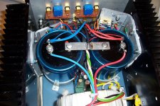
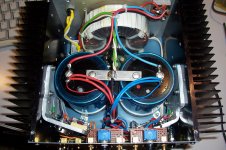
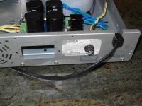
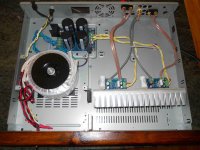
Here is my latest baby: it is a lab amplifier, which means an equipment that will only occasionally reproduce audio, but will mainly serve as power driver for various experiments, 4-quadrants supplies, measurements, emulation of power systems, 400Hz or 60Hz generation, etc, etc.
Once you have tasted the convenience of such an amp, you inevitably become addicted: I have already built a huge number of them but I never have enough.
All the previous versions (except for a notable one) used discrete circuitry, at least for the power section.
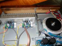
This one is based on LM12's: they are stable, have good performance and include thermal protections impossible to achieve with discrete devices.
Here, the two power channels have an additional protection in the shape of a fast fuse (included in the FB loop). This affords one more protection layer, because such amps are sometimes included in complex setups, with supplies that can widely exceed that of the Opamp itself and require external protection.
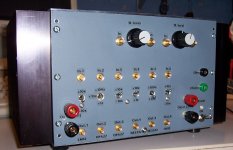
The power channels are configurable as +10 and -10 gain blocks.
4 additional lower power channels are also included:
-two are high-accuracy, based on OPA27's, with one configurable for +1, +10 and +100 gains and the other as +10 or -10
-two are general-purpose, based on the NE5532: one as +1 and +10, the other as +10 or +100.
All the gain-setting resistors are either 0.1%, or have been hand-picked to 0.1% to ensure a good enough accuracy, essential for any lab gear.
The active circuits are complemented with variable attenuators based on high quality potentiometers.
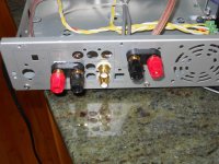
All the coaxial outputs are protected by 50 ohm resistors, and the inputs have series 1K to 5K resistors..
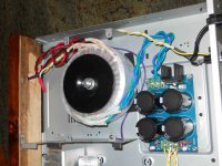
The PSU uses a 200VA/2x22V toroidal and 2 32,000µF capacitors, plus two 20V regulators for the low-power channels: no rocket science, just plain and dependable electronics.
The whole thing is built as a class II device: no earth connection. In addition, the chassis is floating wrt. to the signal ground: this is essential for a test instrument, it gives a maximum of flexibility.
Since the mechanical design is centered on the principal elements, capacitors, heatsinks, transformer, etc, I had the opportunity to size it optimally: large enough to work comfortably, but as small as practical to fit into my already overcrowded lab.
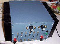
Why use SMB connectors for most interconnects?
They have many advantages from my point of view: they are of the quick connect/disconnect variety, they mate reliably and give excellent contact, they have a controlled impedance, they use very little real-estate (the front panel has 16 of them, and it's far from cramped), and I can have them by the buckets (and the patch-cords too). All this means they are ideal for me.
I have made a tentative here: the heatsinks have a very good anodization, and I used it as an insulator for the LM12's. Risky? Maybe, but I made scratching and 500VDC tests, and they were all conclusive.
If it fails, it will result in a blown fuse, and I can always revert to the good (or not so good) insulation methods.
We will see....
Here is my latest baby: it is a lab amplifier, which means an equipment that will only occasionally reproduce audio, but will mainly serve as power driver for various experiments, 4-quadrants supplies, measurements, emulation of power systems, 400Hz or 60Hz generation, etc, etc.
Once you have tasted the convenience of such an amp, you inevitably become addicted: I have already built a huge number of them but I never have enough.
All the previous versions (except for a notable one) used discrete circuitry, at least for the power section.
This one is based on LM12's: they are stable, have good performance and include thermal protections impossible to achieve with discrete devices.
Here, the two power channels have an additional protection in the shape of a fast fuse (included in the FB loop). This affords one more protection layer, because such amps are sometimes included in complex setups, with supplies that can widely exceed that of the Opamp itself and require external protection.
The power channels are configurable as +10 and -10 gain blocks.
4 additional lower power channels are also included:
-two are high-accuracy, based on OPA27's, with one configurable for +1, +10 and +100 gains and the other as +10 or -10
-two are general-purpose, based on the NE5532: one as +1 and +10, the other as +10 or +100.
All the gain-setting resistors are either 0.1%, or have been hand-picked to 0.1% to ensure a good enough accuracy, essential for any lab gear.
The active circuits are complemented with variable attenuators based on high quality potentiometers.
All the coaxial outputs are protected by 50 ohm resistors, and the inputs have series 1K to 5K resistors..
The PSU uses a 200VA/2x22V toroidal and 2 32,000µF capacitors, plus two 20V regulators for the low-power channels: no rocket science, just plain and dependable electronics.
The whole thing is built as a class II device: no earth connection. In addition, the chassis is floating wrt. to the signal ground: this is essential for a test instrument, it gives a maximum of flexibility.
Since the mechanical design is centered on the principal elements, capacitors, heatsinks, transformer, etc, I had the opportunity to size it optimally: large enough to work comfortably, but as small as practical to fit into my already overcrowded lab.
Why use SMB connectors for most interconnects?
They have many advantages from my point of view: they are of the quick connect/disconnect variety, they mate reliably and give excellent contact, they have a controlled impedance, they use very little real-estate (the front panel has 16 of them, and it's far from cramped), and I can have them by the buckets (and the patch-cords too). All this means they are ideal for me.
I have made a tentative here: the heatsinks have a very good anodization, and I used it as an insulator for the LM12's. Risky? Maybe, but I made scratching and 500VDC tests, and they were all conclusive.
If it fails, it will result in a blown fuse, and I can always revert to the good (or not so good) insulation methods.
We will see....
Attachments
Last edited:
First chip amp from a tube guy
Hi all,
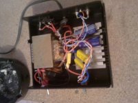
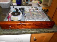
Quite a few years back I purchased some LM3886 boards (two channels and a PS board) for next to nothing (maybe $3US) because they were CHEAP and I had some ebay bucks I wanted to use up. It's basically the chipamp.com circuit. I slowly pulled together parts from my bin (other than the 3886s, the PS tranny and the big caps) and built it over the summer.
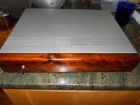
The case was an old DVD/surround sound player that bit the dust and which I modded to work as a chassis for this. Wood is a scrap piece of pine I had around, stained red mahogany (a mistake - I should have left it natural or a more neutral color) and shellac'ed. I'm a card-carrying cheapskate who takes pride in spending as little as possible to get really good sounding music. But this chip-amp thing had me both intrigued and skeptical.
I have to say (against my better tube-loving judgement) that this silly little amp does a surprising job of reproducing music with decent soundstage, great clarity, tight and weighty bass. In short, most of the things I look for. There's a smoothness that it's missing compared to my DIY tube gear, and it seems slightly over-accentuated in certain frequencies (upper mids/vocals in particular). While my Marsh A200 is more balanced overall and probably a bit better with soundstage, the LM3886 has less grain to the sound than the Marsh and the vocals are really present.
For the chump change it took to build, this amp is impressive indeed. Hope the photos make it through.
Hi all,
Quite a few years back I purchased some LM3886 boards (two channels and a PS board) for next to nothing (maybe $3US) because they were CHEAP and I had some ebay bucks I wanted to use up. It's basically the chipamp.com circuit. I slowly pulled together parts from my bin (other than the 3886s, the PS tranny and the big caps) and built it over the summer.
The case was an old DVD/surround sound player that bit the dust and which I modded to work as a chassis for this. Wood is a scrap piece of pine I had around, stained red mahogany (a mistake - I should have left it natural or a more neutral color) and shellac'ed. I'm a card-carrying cheapskate who takes pride in spending as little as possible to get really good sounding music. But this chip-amp thing had me both intrigued and skeptical.
I have to say (against my better tube-loving judgement) that this silly little amp does a surprising job of reproducing music with decent soundstage, great clarity, tight and weighty bass. In short, most of the things I look for. There's a smoothness that it's missing compared to my DIY tube gear, and it seems slightly over-accentuated in certain frequencies (upper mids/vocals in particular). While my Marsh A200 is more balanced overall and probably a bit better with soundstage, the LM3886 has less grain to the sound than the Marsh and the vocals are really present.
For the chump change it took to build, this amp is impressive indeed. Hope the photos make it through.
Attachments
Hello Carl,
Nice job that I agree that a better sound is obtained from using a 'proper' power supply with some large caps. I have two versions one like yours that sounds fat round and engaging and one with just the decoupling caps which sounds a bit austere and remote.
Anyone wanting a 'valve' like sound would be well advised to make something like this, I have friend with a 300B and we both admit that it's got the edge over the GC but we are only talking half a Gnats knacker.
Cheers - Jim
Hi all ... For the chump change it took to build, this amp is impressive indeed. Hope the photos make it through. ...

Nice two by four ...

Seriously, how does it sound?

Thanks, Jim. I haven't tried it without the 20,000uF caps per rail, but I certainly like it this way.
FastEddy,
Close. The wood was from a piece of packaging I had lying around (from windows I think) that happened to have a dado cut along one edge that fit what I needed. About 1 1/8 - 1 1/4 inch thick. Sound? I haven't tried to make music with it yet so I can't say.
Oh, you mean the amp? Can't say much beyond what I said above yet, but so far I'm surprised how much I like it. It may fully supplant my Marsh (which I like but may end up selling to fund my...er...diy habit).
Thanks, Jim. I haven't tried it without the 20,000uF caps per rail, but I certainly like it this way. ... Can't say much beyond what I said above yet, but so far I'm surprised how much I like it. It may fully supplant my Marsh (which I like but may end up selling to fund my...er...diy habit).
Well, most DIY amps sound better than they might if store bought = beauty in the eye of the beholder.
My tda7294 amp
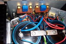
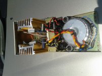
This is the power amp I built usin the tda7294 ic.
for the psu there is a 300va 22-0-22v transformer two 35amp bridge rectifiers and 24700uf capacitance per rail I used 1500uf panasonic FC on the boards with the ic, I used metal film resistors as well.The boards are etched at home too. It has a rather dynamic character, there is also no hum whatsoever, not bad considering it was built using what I had around the shop. What do you think?
Attachments
Thanks Carl, I used the basic application from the data sheet but increased the value of Ci.
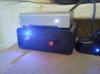
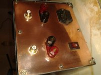
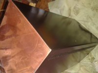
this is the case that I made up from an old ups case and some copper sheet that was in my workshop. The pcb design was from a really bad photo copy that i found online and then cleaned up in paint. I used the toner transfer method on some press and peel film.
this is the case that I made up from an old ups case and some copper sheet that was in my workshop. The pcb design was from a really bad photo copy that i found online and then cleaned up in paint. I used the toner transfer method on some press and peel film.
Attachments

I told myself i was going to wait untill my whole amp is finished. But i can't wait to post my picture here now i finally have something worth posting.
The case is not yet finished, but she's pretty sweet already i think.
You can follow my thread here: http://www.diyaudio.com/forums/chip-amps/257001-introduction-project-info-2.html
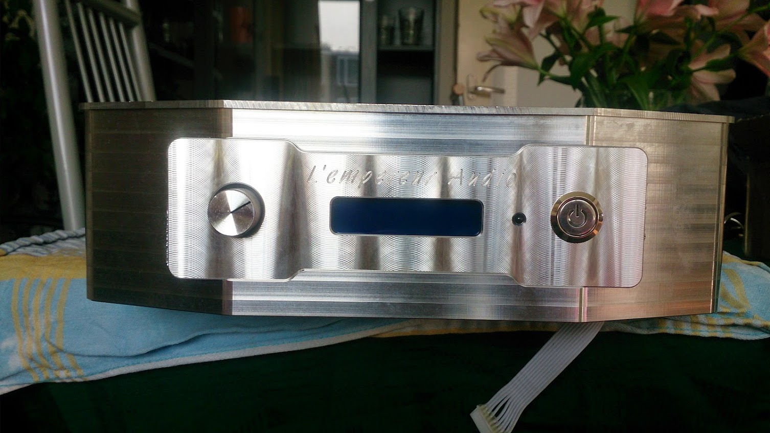
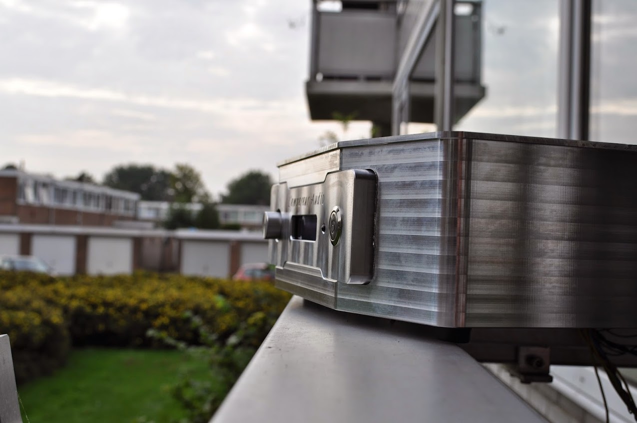
Yes, she really is a ChipAmp
It's a work in progress, but i hope you like to see these pictures
The case is not yet finished, but she's pretty sweet already i think.
You can follow my thread here: http://www.diyaudio.com/forums/chip-amps/257001-introduction-project-info-2.html
Yes, she really is a ChipAmp
An externally hosted image should be here but it was not working when we last tested it.
An externally hosted image should be here but it was not working when we last tested it.
An externally hosted image should be here but it was not working when we last tested it.
An externally hosted image should be here but it was not working when we last tested it.
It's a work in progress, but i hope you like to see these pictures
Last edited:
Pjotter,
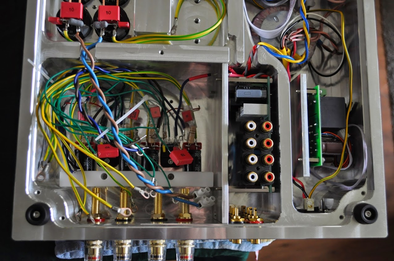
Well, that puts my little project to shame! Incredible. Solid block of aluminum milled? That's WAY beyond my audio budget. But maybe you have connections... Anyway, very nice work. But what about the L channel of input 1? And what of those RCAs sticking out of the bottom? And what chip are you using?
Well, that puts my little project to shame! Incredible. Solid block of aluminum milled? That's WAY beyond my audio budget. But maybe you have connections... Anyway, very nice work. But what about the L channel of input 1? And what of those RCAs sticking out of the bottom? And what chip are you using?
- Home
- Amplifiers
- Chip Amps
- Chip Amp Photo Gallery