Newbie
Hi Guys,
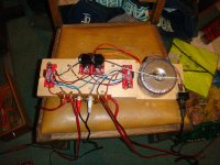
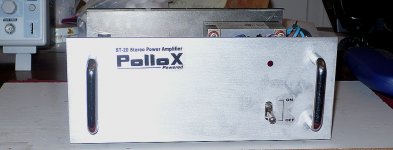
I'm new to the DIY Audio world but after some research i decided to build an LM3886 amplifier, having very little knowledge i found the challenge somewhat daunting.
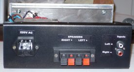
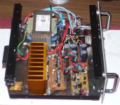
My first prototype is pictured below. I was firstly surprised that it worked!! and pleasantly surprised at the quality of the sound. However, i decided to build 2 mono amps. I picked up a couple of 'kit chassis' as you can see from the photos, the transformers don't quite fit. This is for cooling purposes obviously!!.
My main gripe with these amps is the cheap and wobbly volume control. Has anyone got any good ideas how to dampen them to give a more quality feel?
Please bear in mind that these amps are my first effort.
Hi Guys,
I'm new to the DIY Audio world but after some research i decided to build an LM3886 amplifier, having very little knowledge i found the challenge somewhat daunting.
My first prototype is pictured below. I was firstly surprised that it worked!! and pleasantly surprised at the quality of the sound. However, i decided to build 2 mono amps. I picked up a couple of 'kit chassis' as you can see from the photos, the transformers don't quite fit. This is for cooling purposes obviously!!.
My main gripe with these amps is the cheap and wobbly volume control. Has anyone got any good ideas how to dampen them to give a more quality feel?
Please bear in mind that these amps are my first effort.
Attachments
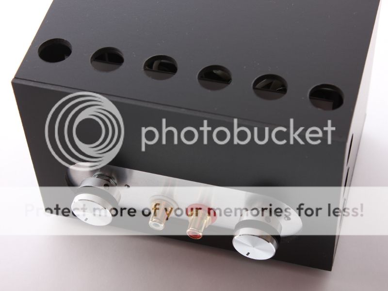
Hi! I've been following this thread for some time and now I'm posting some photographs of a little amplifier intended to be used for my tweeters in a multiamplified system. It's entirely "hand-made" because in my country it's quite difficult to obtain a chassis.


Best whishes!
Best whishes!
Attachments
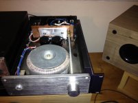
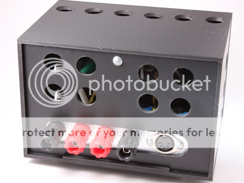
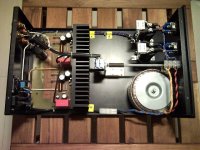
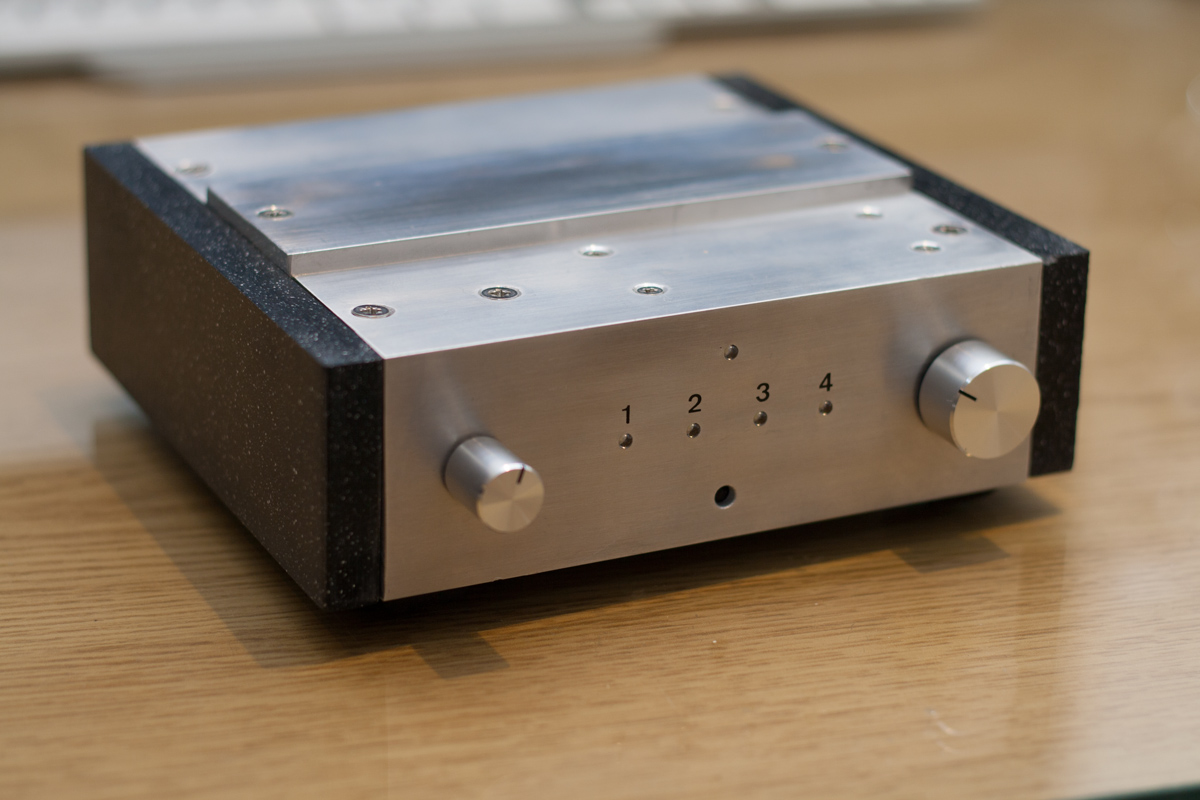
This LM1875 inverted amplifier was built during the New Year holidays. This is my first musical amplifier and it was inspired by projects from Maarten&Annemarie webpage. I call it 'Old Fashioned' because of its chassis-box structure. Works nicely with my AR10pi boxes (set to 1pi, -6dB, -6dB).

Last edited:
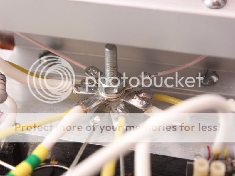
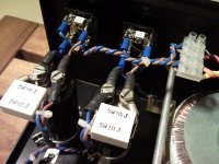
That's what everyone will recognise as a Star Ground.
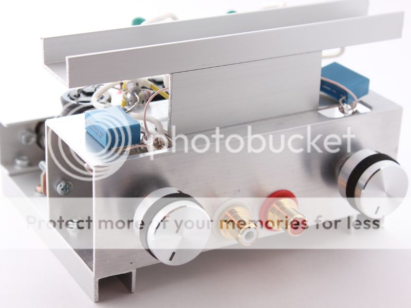
That's output or power star ground. There is also signal star ground on the ground contact of the pot. Can be seen on 4th photo. At first I made one single star ground for everything, but the sound was rather poor. When input ground of the RCA plug was moved to the pot contact, the sound improved. Later I also moved the opamp positive input resistor to this point. Cannot say if this was right thing to do. There are suspicions, that the sound got worse.That's what everyone will recognise as a Star Ground.
Yepper. Nice work. I might've put a lock nut on there. I'm impressed with the chassis work on these last two builds. And ya gotta dig that red heat sink.
gavlar, you ask an interesting question. If you don't want to replace those volume pots, maybe you could place a felt pad between that coupler and internal panel to provide some friction for better feel. I've never really seen this addressed so don't have any answer at the ready. And in the future you may be able to find a lid or can bottom or some such to place over those transformers. You've still earned some props for your first build.
gavlar, you ask an interesting question. If you don't want to replace those volume pots, maybe you could place a felt pad between that coupler and internal panel to provide some friction for better feel. I've never really seen this addressed so don't have any answer at the ready. And in the future you may be able to find a lid or can bottom or some such to place over those transformers. You've still earned some props for your first build.
Yes, this time the guy who sells the metal sheets allowed me to cut and fold them (I guess he was a bit busy). I usually give him a draw and he cuts and folds the sheet for me.. and it is a dirty cheap task, so it's better to let him to do the job@ ezavalla: did you cut and fold that cabinet ?
Looks real Pro.

Yes, it is a ZD14 heatsink.. about 10cm x 5cm tall.. something like 3ºC/W.. but the tweeters level is low, so not to much danger thereI instantly recognized the Delza ZD14 heat sink
It is fitted with a tda2616 chipamp and pga2311 volume ic
Wonderful project! What is the wood / veneer? Very attractive.
Do you have any photos taken during construction?
Cool !!! , but .... show itIt is fitted with a tda2616 chipamp and pga2311 volume ic
Thanks guys... !
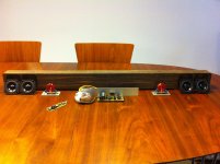
@6L6 - the veneer is ebony. Unfortunately i haven't got any photos from the construction. Stupid really, but when i first get going on a project like this, I can't find the time to grab the camera
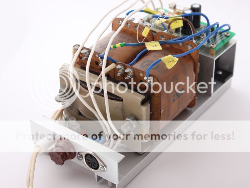
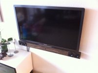
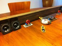
@JMfahey - I have attached a couple of pictures of the system disassembled...
@all - A short description:
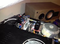
The system is based around the TDA2616 chip amp. The input signal is attenuated/amplified through an PGA2311 volume chip controlled from a Attiny2313 µ-controller. The remote system is based on the rentron TINY-II set.
The speakers are Wavecor Fullrange + subwoofer (cutoff at 1000Hz) to give that extra punch.
Next project is to add a subwoofer to the system. An active subfilter has been incorporated into the main board of the soundbar..
Thanks for looking!
@6L6 - the veneer is ebony. Unfortunately i haven't got any photos from the construction. Stupid really, but when i first get going on a project like this, I can't find the time to grab the camera
@JMfahey - I have attached a couple of pictures of the system disassembled...
@all - A short description:
The system is based around the TDA2616 chip amp. The input signal is attenuated/amplified through an PGA2311 volume chip controlled from a Attiny2313 µ-controller. The remote system is based on the rentron TINY-II set.
The speakers are Wavecor Fullrange + subwoofer (cutoff at 1000Hz) to give that extra punch.
Next project is to add a subwoofer to the system. An active subfilter has been incorporated into the main board of the soundbar..
Thanks for looking!
Attachments
Very nice. Good use of a microprocessor and infra red control.
How is the PGA2311 to work with? I am using IR to control a motorized volume pot and also as a channel selector on a DAC/Pre amp I've almost finished. I would like to use a PGA2311, what is the sound quality like from these chips and do they change the volume smoothly?
How is the PGA2311 to work with? I am using IR to control a motorized volume pot and also as a channel selector on a DAC/Pre amp I've almost finished. I would like to use a PGA2311, what is the sound quality like from these chips and do they change the volume smoothly?
@portreathbeach - Thank you I'm pretty happy with it. As always there are some minor details i probably would have done differently now. But overall its a success.
As to the PGA2311 - After some problems with the SPI (on the ATtiny2313) where solved it works beautifully. No noise what so ever, and the volume is in-/decreased smoothly. However a more smooth volume change could probably be obtained by increasing logarithmic (i think the PGA is changed linear??). Other than the fact that you need to have some understanding for SPI, it's easy to work with And again - the sound quality is great in this system. I can not say that it wouldn't be audible on a $100.000 system. But for this relatively low end it is great
I'm pretty happy with it. As always there are some minor details i probably would have done differently now. But overall its a success.As to the PGA2311 - After some problems with the SPI (on the ATtiny2313) where solved it works beautifully. No noise what so ever, and the volume is in-/decreased smoothly. However a more smooth volume change could probably be obtained by increasing logarithmic (i think the PGA is changed linear??). Other than the fact that you need to have some understanding for SPI, it's easy to work with
And again - the sound quality is great in this system. I can not say that it wouldn't be audible on a $100.000 system. But for this relatively low end it is great Rebuilt my LM3886 chipamp
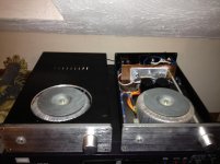
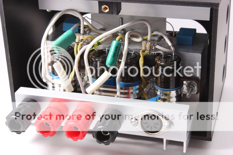
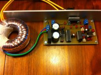
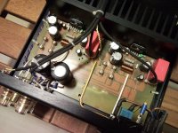
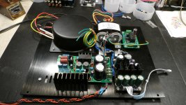
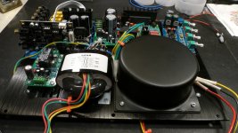
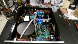
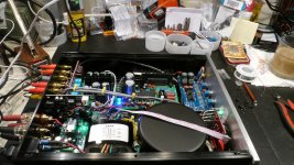
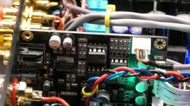
After using my chipamp for some time, the output relay was producing some distorted sound. So I decided to rebuild my chipamp.
Still using the same home made PCB. The PCU capacitance is 33,000uF per rail with f-3dB set at around 35Hz.
After using my chipamp for some time, the output relay was producing some distorted sound. So I decided to rebuild my chipamp.
Still using the same home made PCB. The PCU capacitance is 33,000uF per rail with f-3dB set at around 35Hz.
Attachments
I know I've already posted a pic of my LM4780 chip amp and power supply, but I couldn't resist posting a couple of pics of my DAC/Pre amp I've just finished coupled with my LM4780 amp:
The DAC/Pre amp with IR reciver, motorized pot controlling a Lightspeed Attenuator and channel selector/mute on the left knob using a rotary encoder. All controlled by a PIC16F690 microprocessor.
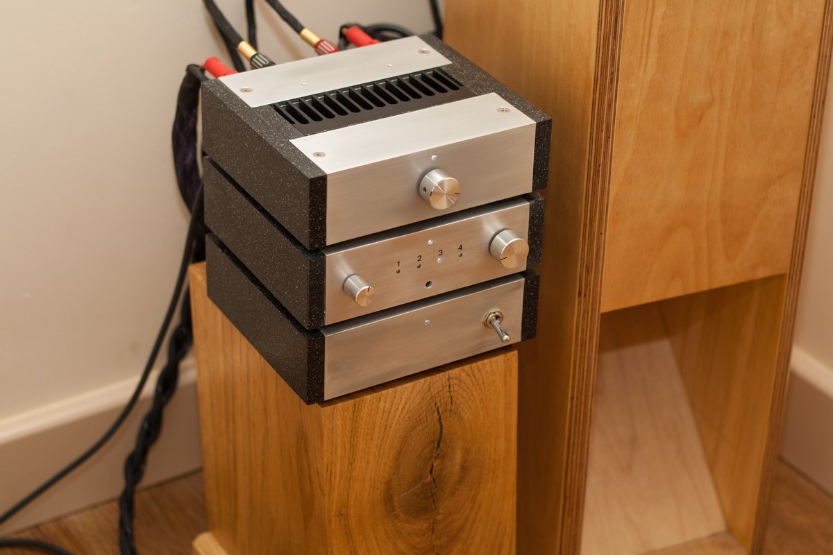
Fits in very nicely with my original PSU and chipamp
The DAC/Pre amp with IR reciver, motorized pot controlling a Lightspeed Attenuator and channel selector/mute on the left knob using a rotary encoder. All controlled by a PIC16F690 microprocessor.
Fits in very nicely with my original PSU and chipamp
My latest integrated amp build
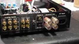
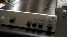
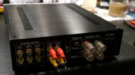
I don't know what drives me to tackle these ambitious projects. Maybe because I can, and enjoy the challenge. Anyway, my latest is an integrated amp with digital-input, based on the Tripath, TA2022 chipamp.
Maybe I take the easy way out, but I prefer modules (from my favorite eBay vendor), over full board builds from the ground up. The amp includes several modules including;
TA2022 amp ~50wpc
NE5532 pre-amp with tone controls
Digital Input and PSU modules
2 Transformers
Speaker Protection module, and
Enclosure
Nothings special about any of the modules, just a modest integrated amp that I wanted to include digital too. I made an expensive boof-up with the front panel, but decided to live with it. I'm the only one who knows! BTW, it was not FPE fault, just my stupid assumption about how the pre-amp controls were layed out. Live and learn. FPE did a great job on the milling and letter of the panels. I did switch out the black knobs for silver after I was done taking pictures.
Anyway, I'm happy with how it turned overall, everything works, and it sounds reasonably well, for what it is, and I'll be using it in my temp housing apt in Danbury, CT while on work assignment.
Here are a few pictures of the progress of my build. Since I wanted to include Pre-Out and Amp-In jacks on the back, note my home-made Johnson plugs in the last picture.
Rick
I don't know what drives me to tackle these ambitious projects. Maybe because I can, and enjoy the challenge.
Anyway, my latest is an integrated amp with digital-input, based on the Tripath, TA2022 chipamp.Maybe I take the easy way out, but I prefer modules (from my favorite eBay vendor), over full board builds from the ground up. The amp includes several modules including;
TA2022 amp ~50wpc
NE5532 pre-amp with tone controls
Digital Input and PSU modules
2 Transformers
Speaker Protection module, and
Enclosure
Nothings special about any of the modules, just a modest integrated amp that I wanted to include digital too. I made an expensive boof-up with the front panel, but decided to live with it. I'm the only one who knows!
BTW, it was not FPE fault, just my stupid assumption about how the pre-amp controls were layed out. Live and learn. FPE did a great job on the milling and letter of the panels. I did switch out the black knobs for silver after I was done taking pictures.Anyway, I'm happy with how it turned overall, everything works, and it sounds reasonably well, for what it is, and I'll be using it in my temp housing apt in Danbury, CT while on work assignment.
Here are a few pictures of the progress of my build. Since I wanted to include Pre-Out and Amp-In jacks on the back, note my home-made Johnson plugs in the last picture.
Rick
Attachments
Last edited:
- Home
- Amplifiers
- Chip Amps
- Chip Amp Photo Gallery