You just power the board with 12V AC? In the ebay description the voltage is specified as: AC 15-18Vx2 (3 lines) + AC 7-12V (2 lines)
following the board traces the 3line connector is for the power supply of the opamps and the 2 line connector is for the digital part only..
following the board traces the 3line connector is for the power supply of the opamps and the 2 line connector is for the digital part only..
Only using 12V DC. And leaving the 18Vs open. I dont have another DAC to reference it with if it is working under-powered. Headphone lines are not working but XLR is working.
I have a transformer lying around that i could use. But confused on 3 pins.
Is the power suppose to be A-B-C with 9-0-9 such that A-B = 9V AC and A-C=18V AC
Thanks
I have a transformer lying around that i could use. But confused on 3 pins.
Is the power suppose to be A-B-C with 9-0-9 such that A-B = 9V AC and A-C=18V AC
Thanks
You just power the board with 12V AC? In the ebay description the voltage is specified as: AC 15-18Vx2 (3 lines) + AC 7-12V (2 lines)
following the board traces the 3line connector is for the power supply of the opamps and the 2 line connector is for the digital part only..
I guess it would be worth a trial to power the board via AC. Not sure how the psus for digital and analog parts are connected, but they shouldn´t be.
usually the A-B-C should be 15-0-15. so your op amps are fed with +15V and -15V (around). If you only have 12V DC available (or even less after the diodes) this is split into +-6V for the opamps. Some of them give better performance with higher voltage, others work fine also with +-6V like eg. op2134 I use with another es9028q2m board.
I have ordered the same board you have a view weeks ago - how is the sound out of the box?
My only references are cheap PCM2704 USB Card and LG V20 Phone going to JBL LSR 305 or apple ear phones. Compared to them i liked these. No hiss or noise.
Without AC, the headphone were not working, now working after connecting (9-0-9 as well as 15-0-15). Connecting AC added extra gain in XLR as well.
For 15-0-15 i picked up old harman kardon AV 40 from goodwill and shucked the transformer but its really bulky. Once you get yours can you check if, Old transformer with, A-B-C-D-E, A-B-C = 9-0-9 and D-E = 36V can be used. I dont have much idea on how AC systems work. Can A-B-C be used as A-C-A or D-E = 36V be used leaving central connector open.
Not sure if there is a typo, and where, but the description of the unbalanced version of the board states "Board power supply: DC 9-18V (2 lines) or AC 7-15V (3 lines)"You just power the board with 12V AC? In the ebay description the voltage is specified as: AC 15-18Vx2 (3 lines) + AC 7-12V (2 lines)
Good to hear it works better now! So you connected 15-0-15 AC to 3pin terminal and 12DC to 2 pin terminal?
usually the middle pin of 3 pin terminal is ground pin, the traces should go directly to both big capacitors. The AC voltage of both outer Pins to the inner Pins should be 15V and the voltage between the both outer Pins should be 30V.
About your transformer I don´t know how it is routed exactly, sorry I cannot help here.. But if you connect AC to the 2-pin terminal use 0-7 or max. 0-12 V.
Hope my board will arrive soon...
Hey, my board arrived today (same as akamikas board)! Connected 15-0-15 and 0-9 VAC. And....very low output level of the outputs. Even with digital "zero". Music is playing, but much too low level..
I changed all opamps, tried different connection orders and all analog outputs, symmetrical and non symmetricals, but very low output level. I measured 29,8V between all V+ and V- pins of opamps and 3,27V output after the LT1963, so no idea what could cause this issue. I only can estimate a wrong vol. set-up of the DAC chip or the controller...what a frustration after all this weeks waiting for the board..
Anybody an idea what could be the reason for this low output level?
My setup is:
Linux (Pulseaudio or Direct Deadbeef) at 0dB -> XMOS -> DAC -> (JBLS 305 via XLR or Apple earpods 23Ohms). Voltage readings are same as yours (5532 opamps are 15V instead of 30).
Two occasions i got real low volumes were:
1. Using only 2.3mm output with only 12V DC In. Connecting XLR on top would make 2.3mm completely silent.
2. XLR output was real low when ground pin on 12V input was very loose or disconnected (Guessing) and there was no AC in.
3. Few occasions everything was silent, fixed by power cycle of 12V input.
I tried AC in for 12V, in my case may be it was faulty transformer in, voltage dropped immediately after connecting. Now using 12V DC. What do you have on receiving end, may be very high impedance ?
Asked seller for schematics and power supply recommendation, no success on any.
Hey, my board arrived today (same as akamikas board)! Connected 15-0-15 and 0-9 VAC. And....very low output level of the outputs. Even with digital "zero". Music is playing, but much too low level..
I changed all opamps, tried different connection orders and all analog outputs, symmetrical and non symmetricals, but very low output level. I measured 29,8V between all V+ and V- pins of opamps and 3,27V output after the LT1963, so no idea what could cause this issue. I only can estimate a wrong vol. set-up of the DAC chip or the controller...what a frustration after all this weeks waiting for the board..
Anybody an idea what could be the reason for this low output level?
I just tried an active mobile speaker with 3,5mm connector, once put into connector terminal and once via cinch adaptor connected to chinch plugs. I checked all my other boards with this speaker before connecting them to my expensive hifi speakers...never had such issue.
Strange, you also had trouble with low volume, but without AC to the opamp supply this seems to be explainable at least..
I will try DC for 2 pin terminal and I also contacted ebay seller..lets see what happans.
Strange, you also had trouble with low volume, but without AC to the opamp supply this seems to be explainable at least..
I will try DC for 2 pin terminal and I also contacted ebay seller..lets see what happans.
Could voltage levels of i2s pins mess up DAC's voltage references or offset line out from DAC ?
also, assuming st chip is microcontroller initializing dac. any fault on chip or its firmware would leave dac in defaults some safe low volume settings.
also, assuming st chip is microcontroller initializing dac. any fault on chip or its firmware would leave dac in defaults some safe low volume settings.
I just tried an active mobile speaker with 3,5mm connector, once put into connector terminal and once via cinch adaptor connected to chinch plugs. I checked all my other boards with this speaker before connecting them to my expensive hifi speakers...never had such issue.
Strange, you also had trouble with low volume, but without AC to the opamp supply this seems to be explainable at least..
I will try DC for 2 pin terminal and I also contacted ebay seller..lets see what happans.
This is my guess aswell that the error is on digital side. I already tried different I2S wires as I had an issue with shielding on my other board. Maybe a mute function is active or level control is set to wrong value by accident...
On other Forum I read on other DAC (I think it was AKM) that the wrong order of powering up digital and analog side could lead to some faulty functions.. Maybe charging time of power caps is too long and could provoke this..? Anybody has an idea?
On other Forum I read on other DAC (I think it was AKM) that the wrong order of powering up digital and analog side could lead to some faulty functions.. Maybe charging time of power caps is too long and could provoke this..? Anybody has an idea?
I got my DAC sing now! I realized after many trials that I have to power the 2 pin connector for digital part AFTER the source signal is active.
My Raspi with hifiberry DAC+pro on top as I2S source is powered with the same transformer as used for the new es9028 board. it takes some time for booting until the driver activates the hifiberry and though the I2S out.
If I connect the 2pin terminal after i2s signal is active, I get full output-level out of my board.
Now I have to see how to delay the 2-pin psu connection or link it with the incoming i2s signal. Any idea is welcome! Is this behaviour normal?
... it takes some time for booting until the driver activates the hifiberry and though the I2S out.
If I connect the 2pin terminal after i2s signal is active, I get full output-level out of my board.
Now I have to see how to delay the 2-pin psu connection or link it with the incoming i2s signal. Any idea is welcome! Is this behaviour normal?
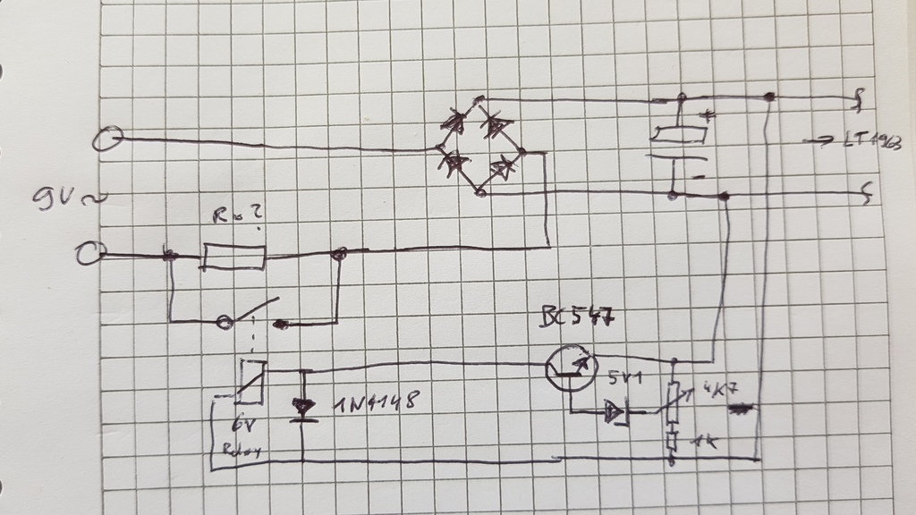
This behavior is normal. What about using one RPi GPIO to switch the power on after booting via relais or transistor?
I have already changed the 5534 to LME49710 and will Change 5532 to LME47920 with a Bypass cap from V- to V+ (100nF film cap). Only with LME49710 the Sound is already better than my other es9028 board with unsymmetrical OP power supply and internal MCKL (and OP2134 and wima DC blocker caps at line out). It is more fine in the heights and has more energy in bass - little darker sounding. Probably also caused by ext. MCKL of higher quality from hifiberry now. I will try to place a Kali between Hbd+p and es9028 board and see if there is a further improvement (I have to use hifiberry because Aroio has no Driver for generic I2S Output).
Regarding the mods for power up, the Image I am using (Aroio with room correction from Abacus) does not allow changes on SW side, so beside my missing skills in Linux it is difficult to apply a GIPO relay control. The 3,3V from Raspi for hifiberry digital are permanent but I could probably make a relay with delay driven by the 5V PSU for Raspi - thanks for this advice - I think I have a relay board with timer still laying around...
Regarding the mods for power up, the Image I am using (Aroio with room correction from Abacus) does not allow changes on SW side, so beside my missing skills in Linux it is difficult to apply a GIPO relay control. The 3,3V from Raspi for hifiberry digital are permanent but I could probably make a relay with delay driven by the 5V PSU for Raspi - thanks for this advice - I think I have a relay board with timer still laying around...
- Home
- Source & Line
- Digital Line Level
- Chinese ES9018K2M I2S DAC