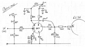
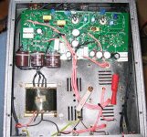
I have one of the cheap china-amplifiers, a copy of this:
http://www.sophiaelectric.com/pages/amp/ampel34.htm
with 2 x 6N1(P) / 4 x EL-34
I have tried to make a schematic of it, and the input-section appears to be like this: (sorry, no expert in making schematics...)
Any suggestions to what can be eaily corrected/modified? or maybe revired for another input-tube?
Any big drawing-errors?
http://www.tubes.ru/techinfo/HiFiAudio/6n1p.html
Arne K
Attachments
Hi,
I think you might have made an error in your schematic. Its a push pull amp right? The 6n1p has to be connected to two el34s maybe at pins 6 & 8? (I guess its one 6N1P per channel?)
Regarding tube substitution; the Russian types are supposed to be rather good to start with, so the benefits might be a bit slight, BUT
If you havent already, have a look at the Duncan amps datasheet locator,
http://tdsl.duncanamps.com/tubesearch.php
Although substitutons seem to be a bit thin the pinout is quite similar to the ECC8* types and they might provide an alternative there, depends what you want to achieve.
Good luck!
Andy
Cobra2 said:I have one of the cheap china-amplifiers, a copy of this:
http://www.sophiaelectric.com/pages/amp/ampel34.htm
Is it me, or is this all weird. Sophia Electric owns a trademark in the phrase "S.E.T." (the serial number is 78163221 which can be looked up at the USPTO, or just search for Sophia Electric) for use with audio equipment which means a) only they can sell audio equipment labeled "S.E.T." and b) it does not mean Single Ended Triode. Instead, it means nothing. So, this amp, called "S.E.T.™ Music EL-34" is actually a push pull amp and is so called because "S.E.T." does not mean anything in this context.
Sorry to thread jack. This just struck me as odd.
Yes the S.E.T. trademark is a bit weird.
In any case I do not really think the cheap China amp is a copy of the Sophia Electric, it is probably rather the Sophia which is a re-branding/OEM of a Chinese amp.
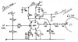
The circuit drawn is obviously not yet correct, but tracing schematics from the live amp is a good exercise.
The 100nf cap is probably connected to the other end of the 300K resistor.
The phase splitter might be a basic paraphase, with the grid of the second triode half being driven by the 330K/20K divider.
The anode of the second triode half (pin 6) will probably go to the other EL34 grid via a 100nF cap.
And I guess there will be some resistor from pin 8 to gnd.
SveinB
In any case I do not really think the cheap China amp is a copy of the Sophia Electric, it is probably rather the Sophia which is a re-branding/OEM of a Chinese amp.
The circuit drawn is obviously not yet correct, but tracing schematics from the live amp is a good exercise.
The 100nf cap is probably connected to the other end of the 300K resistor.
The phase splitter might be a basic paraphase, with the grid of the second triode half being driven by the 330K/20K divider.
The anode of the second triode half (pin 6) will probably go to the other EL34 grid via a 100nF cap.
And I guess there will be some resistor from pin 8 to gnd.
SveinB
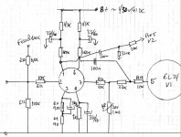
Cobra2 said:output
the resistance reading for the trafo seems odd?
Arne K
Well, maybe not so bad. These are DC resistance readings.
I would expect the secondary to be a little higher, probably more like .5 ohm. Since you have it apart, you should measure also the AC ratio, connect an AC signal to one side and measure on the other. The square of this will be the impedance ratio.
Your diagram is looking better now. The 100nf still need to be connected to the other end of the bottom 330K. Please also check the feedback connection, it is a chance it shouild be connected to the 900/90 ohm cathode resistors.
SveinB
http://www.diyaudio.com/forums/attachment.php?s=&postid=1125355&stamp=1170664733
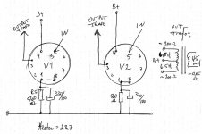
Question from newbee:
B+ to g2/pin4? Is that correct. Pin 3 is the anode, and in triode mode g2 would be tied to anode. In pentode mode g2 is connected to OTP center/B+ via a resistor.
Question from newbee:
B+ to g2/pin4? Is that correct. Pin 3 is the anode, and in triode mode g2 would be tied to anode. In pentode mode g2 is connected to OTP center/B+ via a resistor.
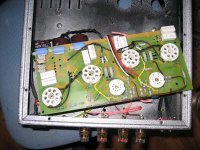
The schematic is hard to read.
As far as what you can do to make it sound better,
first; throw the chinese tubes away (i like holland tubes - tube hop)
second; a real good output transfomer (i like hammond)
last; replace all in signal caps with good ones.
Most Chinese knock offs are based on very good designs just cheap parts.
It might surprise you. I do a bunch of these for freinds.
PSU is a bridge (4x1N4007)and a 150uF/450V cap, splits to each channel, thru a 50 ohm resistor (to each ch) and another 150/450 cap.
The feedback point(resistor) should be connected to the point between R9 & R11.
The 330k resistor between the tubes probably go to gnd, and not between the 10k...
I'm new to tube-audio topologies, and have trouble finding anything similar, all I have seen, have trafos with more taps...
Arne K
@ mississippi, please mail me again, I sent & deleted...and mail bounced (mailbox to small)

Cobra2 said:The 330k resistor between the tubes probably go to gnd, and not between the 10k...
The 330K resistor may be drawn correctly. I think it does not go directly to GND, but via the 20K/10K (trimmer pot?) in order to drive the grid of the second triode half. This is the very old-fasioned paraphase phase splitter used by Yarland and other cheap Chinese amps. It work OK, but needs adjustment when "rolling" driver tubes to get the correct AC signal balance.
Modifying the driver/phase-splitter may be an idea, but I suspect that gain might be marginal with only one double triode per side to drive EL34, so options may be limited.
SveinB
- Status
- This old topic is closed. If you want to reopen this topic, contact a moderator using the "Report Post" button.
- Home
- Amplifiers
- Tubes / Valves
- Chinese EL34 amp to modify