Just wondering if this thread is still alive?
I just have 2 questions about replacing the caps C5,6,7,8,12,13,14,15 in the Lite Dac. I read somewhere that caps are being replaced with ".1uf 63V Polypropylene Film caps". But what does .1uf mean?
Does it mean the caps C5,6,7,8,12,13,14,15 are 0.1uf (100nf)? or 1uf (1000nf)? And the voltage is 63VDC?
And are the caps C38 and C39 different caps? Are they 0,001uf (1nf) and 630VDC. I'm just wondering about the voltage because the caps of C5 etc. are 63VDC.
By the way this is still a good thread! I found a lot of information about the mods and tweaks. Hopefully somebody will answer my question!! Because I want to take the DAC apart and tweak it.
Greetings to old thread.
A dac of many years. I am toying with it due to current dac spoilt. I bypass with a pair of 0.33 sound cap direct to rca and nothing else. Result is distortion. I try to see around but most of bypass done not more then 2 caps. did I miss out something? Many thanks.
Best regards,
Alfred.
A dac of many years. I am toying with it due to current dac spoilt. I bypass with a pair of 0.33 sound cap direct to rca and nothing else. Result is distortion. I try to see around but most of bypass done not more then 2 caps. did I miss out something? Many thanks.
Best regards,
Alfred.
Greetings to old thread.
A dac of many years. I am toying with it due to current dac spoilt. I bypass with a pair of 0.33 sound cap direct to rca and nothing else. Result is distortion. I try to see around but most of bypass done not more then 2 caps. did I miss out something? Many thanks.
Best regards,
Alfred.
try any electrolytic from 1 to 100 uF (preferably 2.2 uF poly cap) just to see if the distortion goes away. neg side to the RCAs.
Alfred,
be sure existing C35 and C36 output caps are disconnected from RCA jacks .
.
For DAC VDD = 6 Volts:
R35, R36 (I/V Resistor) should be 150 Ohm. To accomplish this, solder 150 Ohm parallel to the existing 270 Ohm. With digital input open, adjust VR1 trimpot for 3.3 Volts across I/V resistors.
For DAC VDD = 8 Volts:
R35, R36 (I/V Resistor) should be 270 Ohm, which is already built in. No changes needed. With digital input open, adjust VR1 trimpot for 4.3 Volts across I/V resistors.
Attention: allow DAC to warm up and voltage across I/V resistors to stabilize before adjusting VR1 as voltage may fluctuate as much as 700 mV during warmup.
be sure existing C35 and C36 output caps are disconnected from RCA jacks
.For DAC VDD = 6 Volts:
R35, R36 (I/V Resistor) should be 150 Ohm. To accomplish this, solder 150 Ohm parallel to the existing 270 Ohm. With digital input open, adjust VR1 trimpot for 3.3 Volts across I/V resistors.
For DAC VDD = 8 Volts:
R35, R36 (I/V Resistor) should be 270 Ohm, which is already built in. No changes needed. With digital input open, adjust VR1 trimpot for 4.3 Volts across I/V resistors.
Attention: allow DAC to warm up and voltage across I/V resistors to stabilize before adjusting VR1 as voltage may fluctuate as much as 700 mV during warmup.
try any electrolytic from 1 to 100 uF (preferably 2.2 uF poly cap) just to see if the distortion goes away. neg side to the RCAs.
Hi Whaleman. Before I did anything, originally with active sounds fine. Comparing to my spoilt Shigaraki dac, I found this Lite had an add on buster.
My bad. I bought 4.7uf sound cap and resistors too to try up after I passive this dac. The distortion was very bad that hardly audible. I found out it caused by removing AC 18 0 18 power input which I plug it off, thinking the active side no longer in use. Now all are okie. Many thanks.
Alfred,
be sure existing C35 and C36 output caps are disconnected from RCA jacks
For DAC VDD = 6 Volts:
R35, R36 (I/V Resistor) should be 150 Ohm. To accomplish this, solder 150 Ohm parallel to the existing 270 Ohm. With digital input open, adjust VR1 trimpot for 3.3 Volts across I/V resistors.
For DAC VDD = 8 Volts:
R35, R36 (I/V Resistor) should be 270 Ohm, which is already built in. No changes needed. With digital input open, adjust VR1 trimpot for 4.3 Volts across I/V resistors.
Attention: allow DAC to warm up and voltage across I/V resistors to stabilize before adjusting VR1 as voltage may fluctuate as much as 700 mV during warmup.
Hi Karstenpg,
C35 and C36,
I removed the connection directly from the RCA, but left the negative intake. Therefore I didn't remove this 2 caps.
Dac Vdd 6, and Vdd 8,
Please enlighten me why I need to choose either both of this. I measure pin 5 and read 5.9v. I had replace R35 and R36 to 180 ohm. I do that because a quick read thru to old posting hoping to solve the bad distortion issue but after hook back 18 0 18 all are fine. Currently adjust to 3.3v for pin 8 and 6.
Dac warm up.
Yes, thank you. after warm up it drops to 3.1 so I adjust it back to 3.3v.
1)Now, my itchy hand. How am I gona remove all active parts since without plug in AC 18 0 18, it distorted. I cant get it. Since not using active why the main ac disturb the sound. My reason of removing the active part because of tight area for mounting huge sound caps in future.
2)I think x8 is unnecessary. I want to remove at least half of it for other project since last year CAD had make a 1543 x 16 cost near 7000 pound. Is it 1543 reborn? I see thru the schematic, 2 psu feeds 4 each side. If I cut down, should I go for 2 psu left 2 dac each side, or 1 psu for x 4.
Really appreciate your help.
Best regards,
Alfred.
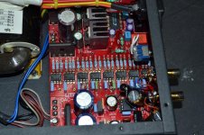
I have to admit that I went back to the active output and prefer it. I upgraded the op amps to TI OPA2604 (single channel version) and I found it very pleasing, very nice mids. I also decided to go with Nichicon Muse output caps bypassed with some very small Sonicap Platinums.
Glad you found your problem. I think the passive mod is matter of taste and it may not be for everyone. You can always add a second set of RCAs (as I did) and have both available on your amp selector switch. Once I found myself never using the passive output, I removed it and the RCAs. The leftover holes provide good ventilation.
Glad you found your problem. I think the passive mod is matter of taste and it may not be for everyone. You can always add a second set of RCAs (as I did) and have both available on your amp selector switch. Once I found myself never using the passive output, I removed it and the RCAs. The leftover holes provide good ventilation.
Attachments

Hi Whaleman,
True, it is all about taste. My hook up is shigaclone transport, lite and gainclone. I found out that the dynamic, (crescendo) if gainclone is superb that a mellow dac match quite well.
Btw, I still plan to remove the active parts. If someone can help me pls, advise. I might plan to install my long bought I tube zator output stage. Hope it can improve my know how in dac by toying with it.
Best,
Alfred.
Hi Whaleman,
True, it is all about taste. My hook up is shigaclone transport, lite and gainclone. I found out that the dynamic, (crescendo) if gainclone is superb that a mellow dac match quite well.
Btw, I still plan to remove the active parts. If someone can help me pls, advise. I might plan to install my long bought I tube zator output stage. Hope it can improve my know how in dac by toying with it.
Best,
Alfred.
This is all there is to the passive out. No need to remove anything, just add 2 caps and 2 RCAs. You will have to drill holes, or disconnect the existing RCAs.
Attachments
Alfred,
VDD = 6 V / 8 V:
There are two versions of DAC-AH. One has 6 V regulators (apparently yours), the other one has 8 V regulators. As per TDA1543 datasheet, with VDD = 6 V, 150 Ohm is the correct value for the I/V resistor.
If you disconnect 18-0-18 VAC from the board, you must cut the input leads to each opamp or better desolder both opamp chips.
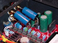
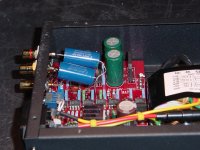
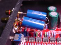
However, my DAC-AH uses AD847 opamps and I prefer using these in the attached manner. I regard this solution superior to the simple passive output.
Note that I did cut all 8 Vref leads and use a separate fixed Zener input bias to the opamp +input pin 3, one for each opamp. The reason for cutting the Vref leads is that it is difficult to understand the interaction between the 8 DAC chips tied to a common Vref rail, each with a slightly different intrinsic Vref voltage. Creating separate and DAC independent offset voltages for each AD847 should reduce harmonics and crosstalk.
For output caps C35, C36 I use non-fancy standard small WIMA MKS-2 polyester type with 5% tolerance.
VDD = 6 V / 8 V:
There are two versions of DAC-AH. One has 6 V regulators (apparently yours), the other one has 8 V regulators. As per TDA1543 datasheet, with VDD = 6 V, 150 Ohm is the correct value for the I/V resistor.
If you disconnect 18-0-18 VAC from the board, you must cut the input leads to each opamp or better desolder both opamp chips.
However, my DAC-AH uses AD847 opamps and I prefer using these in the attached manner. I regard this solution superior to the simple passive output.
Note that I did cut all 8 Vref leads and use a separate fixed Zener input bias to the opamp +input pin 3, one for each opamp. The reason for cutting the Vref leads is that it is difficult to understand the interaction between the 8 DAC chips tied to a common Vref rail, each with a slightly different intrinsic Vref voltage. Creating separate and DAC independent offset voltages for each AD847 should reduce harmonics and crosstalk.
For output caps C35, C36 I use non-fancy standard small WIMA MKS-2 polyester type with 5% tolerance.
Attachments
I once owned a Dac AH when it first came out, and here's what I posted on head fi. Don't know if they changed the design since then.
Hope this helps
I received my Dac Ah this week and, after correcting the output resistors to 148 ohms (for the V supply) and tweaking the offset pot for 3.3V dc at the combined dac output to center the dynamic range, I have to say I was very disappointed. It sounded somewhat distorted and the bass would lose control
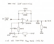
So, I dug back inside the Dac Ah and turfed the output op amp with the passive mod well described by Kim in another thread. I’m not fond of the dac ah’s o/p stage: it uses a non-inverting op amp with no dc block on the input. Effectively, the +ve and –ve leads are imbalanced by the dac dc o/p, 3.3V. Even the TDA spec sheet shows the better implementation, an inverting op amp with the +ve lead biased up by Vref. My unit was also shipped with AD847 high speed op amps. The original cct called for 5532s, and the 847s are much more particular about layout. For all I know the 847s may be oscillating (no high speed scope at home or I would have checked, bu there's allot of hash in the high frequencies of the THD plot, before the mod).
Instead of depopulating the op amp, I connected its output to ground through a 2.4kohm resistor (the 847 likes to see >1kohm), and ran a 3.3 uF good quality poly cap off the dac o/p to the RCA jack. This is going to be used with a Govibe 5, which has an input impedance of 8.75kohm at full volume, and 9.5kohm at min. The 3.3uF was the min size, to avoid premature bass roll-off.
I hooked it back up and instantly: BANG! THIS is what everyone’s been talking about! Before the passive mod, the drums on Kyuss’ “Thong Song” sounded like they were about to explode into tinder, and the strings of the guitar on the Beasts of Bourbon “Not Gonna Try No More” sounded like they were scraping against the fret board. Mids are now forward, but not too bad and the high’s cleaned right up. The thing’s still a bass monster, the DT770 of dacs") but it’ll make a decent dac for work.
but it’ll make a decent dac for work.
Here’s a final THD measure after the passive mod attached
The picture doesn't come close to doing the change justice, but what does stick out is that the nasty 7th has decreased significantly, as has all the “hash” up at the top end. I don’t know if this explains the difference, but it’s a good thing. The pictures also show that about 6 dB output is lost with the passive mod.
In the end, I think I’ll be happy with the dac ah, but out of the box it’s fatally flawed:
- wrong dac output resistors so output clips
- wrong reference voltage bias so it clips asymmetrically (+ve peaks don’t clip at the same levels as –ve peaks)
- very high speed op amps were used in a design proven in with low speed ones, without adding any required decoupling caps on the power pins
- it uses a flat out dumb output stage design
The bass is still a bit silly (exaggerated and not that tight), but eq helps.
Hope this helps
I received my Dac Ah this week and, after correcting the output resistors to 148 ohms (for the V supply) and tweaking the offset pot for 3.3V dc at the combined dac output to center the dynamic range, I have to say I was very disappointed. It sounded somewhat distorted and the bass would lose control
So, I dug back inside the Dac Ah and turfed the output op amp with the passive mod well described by Kim in another thread. I’m not fond of the dac ah’s o/p stage: it uses a non-inverting op amp with no dc block on the input. Effectively, the +ve and –ve leads are imbalanced by the dac dc o/p, 3.3V. Even the TDA spec sheet shows the better implementation, an inverting op amp with the +ve lead biased up by Vref. My unit was also shipped with AD847 high speed op amps. The original cct called for 5532s, and the 847s are much more particular about layout. For all I know the 847s may be oscillating (no high speed scope at home or I would have checked, bu there's allot of hash in the high frequencies of the THD plot, before the mod).
Instead of depopulating the op amp, I connected its output to ground through a 2.4kohm resistor (the 847 likes to see >1kohm), and ran a 3.3 uF good quality poly cap off the dac o/p to the RCA jack. This is going to be used with a Govibe 5, which has an input impedance of 8.75kohm at full volume, and 9.5kohm at min. The 3.3uF was the min size, to avoid premature bass roll-off.
I hooked it back up and instantly: BANG! THIS is what everyone’s been talking about! Before the passive mod, the drums on Kyuss’ “Thong Song” sounded like they were about to explode into tinder, and the strings of the guitar on the Beasts of Bourbon “Not Gonna Try No More” sounded like they were scraping against the fret board. Mids are now forward, but not too bad and the high’s cleaned right up. The thing’s still a bass monster, the DT770 of dacs
but it’ll make a decent dac for work.Here’s a final THD measure after the passive mod attached
The picture doesn't come close to doing the change justice, but what does stick out is that the nasty 7th has decreased significantly, as has all the “hash” up at the top end. I don’t know if this explains the difference, but it’s a good thing. The pictures also show that about 6 dB output is lost with the passive mod.
In the end, I think I’ll be happy with the dac ah, but out of the box it’s fatally flawed:
- wrong dac output resistors so output clips
- wrong reference voltage bias so it clips asymmetrically (+ve peaks don’t clip at the same levels as –ve peaks)
- very high speed op amps were used in a design proven in with low speed ones, without adding any required decoupling caps on the power pins
- it uses a flat out dumb output stage design
The bass is still a bit silly (exaggerated and not that tight), but eq helps.
Attachments
Speaking of "my DAC-AH" with AD847 I/V-opamps: altogether I have modified four DAC-AH, one with AD847 as described in post #34, one with a slightly modified circuit (bias circuit, feedback resistor, output divider, see post #7) and two with the LME49713 (see post #10). I use the two LME49713 mods myself, the two AD847 based mods are used by family members living farther away.
A note on passive I/V: the TDA1543 data sheet specifies a typical AC compliance of +- 25 mV. This means, the AOL and AOR outputs must stay within a +-25 mV window even when a 0 dB AC digital signal is applied to the TDA1543 input. Obviously, this cannot be accomplished by a simple resistor I/V circuit. Instead, it requires a transimpedance opamp circuit with a stable input summing junction like the one in the TDA1543 data sheet. This is probably the reason why the passive I/V is not broadly appreciated.
A note on passive I/V: the TDA1543 data sheet specifies a typical AC compliance of +- 25 mV. This means, the AOL and AOR outputs must stay within a +-25 mV window even when a 0 dB AC digital signal is applied to the TDA1543 input. Obviously, this cannot be accomplished by a simple resistor I/V circuit. Instead, it requires a transimpedance opamp circuit with a stable input summing junction like the one in the TDA1543 data sheet. This is probably the reason why the passive I/V is not broadly appreciated.
Speaking of "my DAC-AH" with AD847 I/V-opamps: altogether I have modified four DAC-AH, one with AD847 as described in post #34, one with a slightly modified circuit (bias circuit, feedback resistor, output divider, see post #7) and two with the LME49713 (see post #10). I use the two LME49713 mods myself, the two AD847 based mods are used by family members living farther away.
A note on passive I/V: the TDA1543 data sheet specifies a typical AC compliance of +- 25 mV. This means, the AOL and AOR outputs must stay within a +-25 mV window even when a 0 dB AC digital signal is applied to the TDA1543 input. Obviously, this cannot be accomplished by a simple resistor I/V circuit. Instead, it requires a transimpedance opamp circuit with a stable input summing junction like the one in the TDA1543 data sheet. This is probably the reason why the passive I/V is not broadly appreciated.
My previous post compared the two distortion plots and I was able to get full scale output (with less gain) passively modded, and much lower distortion, than active.
@ DDF:
Did you compare your passive mod with the original circuit ?My previous post compared the two distortion plots and I was able to get full scale output (with less gain) passively modded, and much lower distortion, than active.
Hi guys,
Tq for the inputs of both passive and active. Frankly some are beyond my knowledge but very enlightening.
I am lucky, that I can AB compare to Shigaraki dac which was not that spoilt. Only a digital input pin was broken. Hook it up and well, Lite have it's interesting sound.
I go a bit further, somehow hope I don't destroy it last 2 days. First, I removed all active components and ac input. Ya, no longer sound short distortion and back to normal but weak knees. Very tempting vocals. Nothing much things had replaced. Iv used 180ohm (due to no stock for 160 ohm. Output caps simple at 4.7uf and that is it. Comparing to Shigaraki still the gain and dynamic not there. Shigaraki sound harsher.
Yesterday was abit insane. I removed one of the psu feeding x4 chips. (the far right inclusive of heat sink, regulator. Worsen, weaker gain but very smooth. Due to this, my gainclone don't runs that hot. : Today I will again, remove all filter resistor and use cable jumper (which I don't think it is nessesary). Change to 08 instead of 06, and hook back 270 ohm. See how it goes.
- Status
- This old topic is closed. If you want to reopen this topic, contact a moderator using the "Report Post" button.
- Home
- Source & Line
- Digital Line Level
- Chinese DAC-AH new modifications