Maybe this isn't the right forum, if not, mods please move 
I'm modifying a commercial roaster. The hardware is good, but the control software is not. I'm in process of modifying the circuit board to accept standard third party control hardware and software. I believe what I'm doing is relatively simple, but wanted to check with others.
I'd like to patch the new hardware's control signals in at two optoisolators (MOC3023) on the existing circuit boards. The issue is that the new hardware references earth ground, while the existing circuit board uses a floating ground. I've looked at the optoisolator data sheet (https://www.onsemi.com/pdf/datasheet/moc3023m-d.pdf) and it looks like I can simply cut the two optoisolators free from the floating ground, and then connect the signal-in and earth-referenced ground from the new hardware.
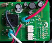
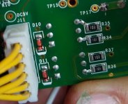
I've taken some pictures. The first picture shows the floating ground, highlighted in green. I've included a picture of the back side of the circuit board, showing what I believe are two clamping diodes on the inputs of the optoisolators. I want to cut the trace at the red line to separate the optoisolators from the floating ground. Should work? Any thoughts?
I'm modifying a commercial roaster. The hardware is good, but the control software is not. I'm in process of modifying the circuit board to accept standard third party control hardware and software. I believe what I'm doing is relatively simple, but wanted to check with others.
I'd like to patch the new hardware's control signals in at two optoisolators (MOC3023) on the existing circuit boards. The issue is that the new hardware references earth ground, while the existing circuit board uses a floating ground. I've looked at the optoisolator data sheet (https://www.onsemi.com/pdf/datasheet/moc3023m-d.pdf) and it looks like I can simply cut the two optoisolators free from the floating ground, and then connect the signal-in and earth-referenced ground from the new hardware.
I've taken some pictures. The first picture shows the floating ground, highlighted in green. I've included a picture of the back side of the circuit board, showing what I believe are two clamping diodes on the inputs of the optoisolators. I want to cut the trace at the red line to separate the optoisolators from the floating ground. Should work? Any thoughts?