After prolonged listening I noticed some differences in reproduction.First , sound picture is slightly darker with both snubbers.I would say less attractive than before, with reduced body of the instruments and vocals. But it seems that some pleasant coloration is removed. Bass is drier, but firmer and the whole sound is more coherent.More neutral and less forward in midrange.
Many people would prefer unsnubbered power supply.It gives so called warmer sound which many like.My flatpack transformers with very high L are sensitive to ringing. My other phonostage with unsnubbered low L torodial have dry, precise sound picture similar to snubbered flatpack. But , it takes time for testing with various music styles. Quick conclusions are bad.
Many people would prefer unsnubbered power supply.It gives so called warmer sound which many like.My flatpack transformers with very high L are sensitive to ringing. My other phonostage with unsnubbered low L torodial have dry, precise sound picture similar to snubbered flatpack. But , it takes time for testing with various music styles. Quick conclusions are bad.
You have performed two listening tests at two different amounts of transformer ringing. Maybe you will enjoy the sound even more when the amount of ringing is increased further, beyond the "no resistor and no snubber at all" amount of ringing.
Why assume that the manufacturer of your flatpack transformer just accidentally happened to build a transformer whose leakage inductance just happens to be the optimum value (not too high, not too low, just exactly right) which gives the best sound? You could increase the ringing amplitude by adding an inductor in series with your transformer secondary, and then listening to see whether the sound is better or not.
Why assume that the manufacturer of your flatpack transformer just accidentally happened to build a transformer whose leakage inductance just happens to be the optimum value (not too high, not too low, just exactly right) which gives the best sound? You could increase the ringing amplitude by adding an inductor in series with your transformer secondary, and then listening to see whether the sound is better or not.
Last edited:
Both single resistor and CRC snubber gave almost the same ringing amplitude on scope, and I described sound with them as more neutral. I do not understand you fully.Purpose of your jigs are to reduce ringing and potential noise and distortion and now you suggest increasing amount of ringing.
I said that unsnuberred circuit had pleasant coloration which some people prefer , not me.I hope that you are not sarcastic.In fact I am sure you are.
I said that unsnuberred circuit had pleasant coloration which some people prefer , not me.I hope that you are not sarcastic.In fact I am sure you are.
I can really recommend the Cheapomodo. I bought a kit from Mark, the delivery was fast and it is an easy build. Attached is the measurement om my Toroidy 1600VA 4x50V transformer without snubber and with snubber resistor Rs=15 ohm. Cx=10nF and Cs=150nF. I shorted the primary and the three other secondaries.


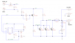
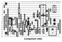
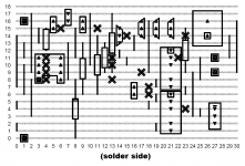
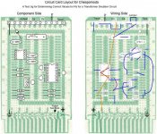
I implemented Cheapomodo today on Stripboard / Veroboard, using the VeeCAD software mentioned here. I built it on a very inexpensive 94mm x 53mm piece of Stripboard that I bought from Tayda for $0.66 (link). The resulting Cheapomodo worked perfectly.
I've attached the VeeCAD schematic and the stripboard layout below, in case another member may want to build a Cheapomodo on Veroboard, someday.
_
I've attached the VeeCAD schematic and the stripboard layout below, in case another member may want to build a Cheapomodo on Veroboard, someday.
_
Attachments
Cheapomodo Problem
I am coming to the Quasimodo and Cheapomodo discussions quite late, but thought that my experiences might be useful to other newbies. I am preparing to build a pair of mono amps around AmpsLab Hx200 circuit cards, and needed a power supply, which brought me to diyaudio’s universal power supply card, which brought me to the two discussion threads.
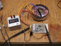
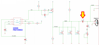
I built my Cheapomodo version 3 on a DIP Vero card. I had to buy the 2N7000 MOSFETs, but otherwise I had all the necessary parts. I used a 100 ohm trimmer pot because on reading many posts it seemed that I would be working at the very low end of a 1K trimmer. And as it turned out, I ended up setting the trimmer as low as it would go (0.31 ohms) and then used an external resistor substitution box with 1-ohm steps to get the resolution I needed. The transformer was a Triad 500 VA toroidal (VPT100-5000). I am operating my Cheapomodo at 10V from a bench power supply ( HP E3616A). However all my results are essentially identical if I use a 9V battery.
I have attached a photo of my setup, drawings of the circuit card, and three scope photos. The first scope photo is with the substitution box set for 0 ohms. The second scope photo is with the substitution box set for 10 ohms, which I consider very close to zeta = 1. And finally the third scope photo is with no resistance at all, showing NO ringing.
Based on my reading of Mark’s original design note on Quasimodo and many contributions to these discussions I should be seeing just the opposite, ringing should occur with infinite resistance for Rs and the ringing should be progressively dampened as the resistance is decreased. I see exactly the opposite with my setup.
I have been working this problem for about a week. I tried smaller EI transformers, I replaced the power supply with a 9V battery, I double checked my card wiring, always the same result, no ringing with Rs set for infinite resistance.
I am out of my depth here so a little nudge in the right direction would be appreciated.
Thanks,
ceulrich
I am coming to the Quasimodo and Cheapomodo discussions quite late, but thought that my experiences might be useful to other newbies. I am preparing to build a pair of mono amps around AmpsLab Hx200 circuit cards, and needed a power supply, which brought me to diyaudio’s universal power supply card, which brought me to the two discussion threads.
I built my Cheapomodo version 3 on a DIP Vero card. I had to buy the 2N7000 MOSFETs, but otherwise I had all the necessary parts. I used a 100 ohm trimmer pot because on reading many posts it seemed that I would be working at the very low end of a 1K trimmer. And as it turned out, I ended up setting the trimmer as low as it would go (0.31 ohms) and then used an external resistor substitution box with 1-ohm steps to get the resolution I needed. The transformer was a Triad 500 VA toroidal (VPT100-5000). I am operating my Cheapomodo at 10V from a bench power supply ( HP E3616A). However all my results are essentially identical if I use a 9V battery.
I have attached a photo of my setup, drawings of the circuit card, and three scope photos. The first scope photo is with the substitution box set for 0 ohms. The second scope photo is with the substitution box set for 10 ohms, which I consider very close to zeta = 1. And finally the third scope photo is with no resistance at all, showing NO ringing.
Based on my reading of Mark’s original design note on Quasimodo and many contributions to these discussions I should be seeing just the opposite, ringing should occur with infinite resistance for Rs and the ringing should be progressively dampened as the resistance is decreased. I see exactly the opposite with my setup.
I have been working this problem for about a week. I tried smaller EI transformers, I replaced the power supply with a 9V battery, I double checked my card wiring, always the same result, no ringing with Rs set for infinite resistance.
I am out of my depth here so a little nudge in the right direction would be appreciated.
Thanks,
ceulrich
Attachments
First of all, there is definitely something wrong with the "Infinite Ohms" setup. Notice that the green trace, channel 2, is offset by +3V DC at the left edge of the picture. This is wildly incorrect; the scope probe is attached to a node that is AC coupled to the rest of the circuit (by Cx); it "cannot" have a DC offset. In the other two pictures of post #188, channel 2 indeed does not have a DC offset; at the left of the photo, it is at ground.
I recommend connecting up the "infinite" case again, and troubleshooting.
Maybe there are other problems too, but this problem really jumps out, making it a good place to start.
_
I recommend connecting up the "infinite" case again, and troubleshooting.
Maybe there are other problems too, but this problem really jumps out, making it a good place to start.
_
Attachments
Cheapomodo Problem Fixed
Mark, many thanks for the guidance! I am embarrassed to admit that after about 15 minutes of probing (with a dental pick) I found a cold solder joint on one of the connections between the terminal strip and the board. It was one of the connections for the transformer. After touching up that joint my problems went away. The circuit now operates just as described. The attached scope photo one shows Rs = infinity, scope photo two shows Rs = 40 ohm, and scope photo three shows Rs = 35 ohms, and scope photo four shows Rs = 30 ohms. I like 30 ohms for zeta = 1.
Mark, many thanks for the guidance! I am embarrassed to admit that after about 15 minutes of probing (with a dental pick) I found a cold solder joint on one of the connections between the terminal strip and the board. It was one of the connections for the transformer. After touching up that joint my problems went away. The circuit now operates just as described. The attached scope photo one shows Rs = infinity, scope photo two shows Rs = 40 ohm, and scope photo three shows Rs = 35 ohms, and scope photo four shows Rs = 30 ohms. I like 30 ohms for zeta = 1.
Attachments
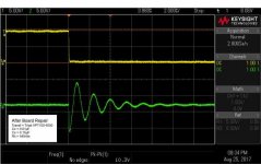
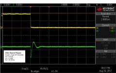
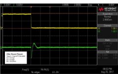
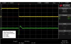
Excellent results, congratulations! Your scope probe ground connection looks especially good, with no artifacts at all: a perfect falling edge on the yellow trace.
BTW check your manual to see whether the scope will output screen capture images in .PNG file format. Mine does, and they are ultra crisp & beautiful, with file size only 30 kBytes. JPEGs are sometimes blurry. diyAudio supports upload and display of .PNG files.
BTW check your manual to see whether the scope will output screen capture images in .PNG file format. Mine does, and they are ultra crisp & beautiful, with file size only 30 kBytes. JPEGs are sometimes blurry. diyAudio supports upload and display of .PNG files.
Have you heard any difference /improvement in reproduced sound?I've been using the Cheapmodo and updating preamp, dacs, tuner, power amps etc. It's fast and easy to use. Many thanks Mark!
Have you heard any difference /improvement in reproduced sound?
¿Lower intermodulation?


- Status
- This old topic is closed. If you want to reopen this topic, contact a moderator using the "Report Post" button.
- Home
- Amplifiers
- Power Supplies
- CheapoModo: quick and dirty transformer snubber bellringer jig