There is another aspect of NOS not mentioned here yet. Removing digital filter forces to heavy analogue filtering. And it needs parts, parts, parts. The heavier filtering, the more parts needed. And each little part affects the sound. Of course one can put in Duelund capacitors and Caddock resistors, but it costs fortune and are physically big like dinosaurs.
So I prefer to use the best digital filter I can achieve and use only one best capacitor I can buy per channel.
So I suppose the reason of Audio Note DAC 1.1x sound failure lays in upper right corner of this green PCB:
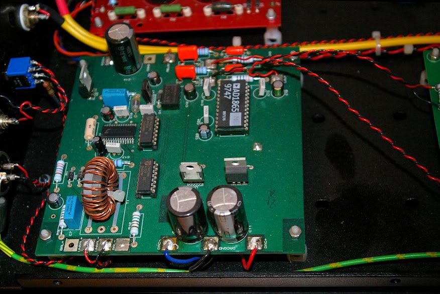
There is analogue filtering based upon some cheap Philips MKT capacitors. That must affect the sound by much.
So I prefer to use the best digital filter I can achieve and use only one best capacitor I can buy per channel.
So I suppose the reason of Audio Note DAC 1.1x sound failure lays in upper right corner of this green PCB:
There is analogue filtering based upon some cheap Philips MKT capacitors. That must affect the sound by much.
I suspect the reason this sounds poor is the grounding - I can only see a single ground plane. DAC grounding for decent sound is an art. The grounding is going to make a bigger difference to the sound than the caps - by all means change the caps (NP0 ceramics sound fine to me and are much cheaper than the currently fashionable boutique caps) but only after optimizing the grounding and supplies. I can't see any local regulation for the DAC itself, that's not a good sign.
Oh and if that large toroid is an S/PDIF transformer, change it to something smaller and lower capacitance.
Oh and if that large toroid is an S/PDIF transformer, change it to something smaller and lower capacitance.
Look at this:

I don't suppose it has any better grounding than that in Audio Note DAC 1.1x.
The power supply is also very primitive, only three ugly regulators 7805/7905.
With this simple PCB I achieved very good sound with passive I/V conversion and simple tube gain stage, no analogue filtering at all. Hardly played with this PCB. The signal capacitors at the output of tube stage makes HUGE difference in sound quality. Also the resistors in I/V conversion makes big difference. The type of regulators and capacitors in power supply makes very little difference, or even no difference at all. The rectifier type makes significant difference and SBYV27 I found best.
So, in general, I dissagree the grounding issue could do so big havoc in sound of AN DAC1.1x and I persist in that the poor analogue filtering was a cause.
That board looks to have much better grounding than the earlier one. There's a digital ground (to the right) and thick tracks (on the left) which I take to be grounds. Not at all hard to see why this one sounds better. I can't see the tracks on the underside though - in particular the output tracks for 0V need to be starred.
That is not ground, that is +5V supply line.That board looks to have much better grounding than the earlier one. There's a digital ground (to the right)
Those are not grounds, those are +5V and -5V supply lines.and thick tracks (on the left) which I take to be grounds.
No star grounding on underside.Not at all hard to see why this one sounds better. I can't see the tracks on the underside though - in particular the output tracks for 0V need to be starred.
I have this DAC board with passive I?V and tube stage and it sounds heavenly, so I definitive stopped to search any digital source.
Hi, are you taking advantage and using both (+ and -) signals from your PCM1798 into your tube output stage or just one phase of the signal?
can you share a simple basic schematic and what type of tube are you using for I/V and gain stage? I might try this diy project to compare it to an CS4397/8
Thanks
The underside are two continuous ground planes tied together between regulators. The border line lies between filter and DAC.
The digital and analogue ground pins of AD1865 are tied together at the chip, not according to grounding recommendations stated in the datasheet. So this PCB is very ugly designed, but the ground issues could not destroy sound quality. I was to lazy to make it from scratch only to taste AD1856 sound.
By the way, I always completely remove S/PDIF transformers as they affects the sound quality.
I tried to use both phases of the signal from DAC, but found no advantage in sound quality. On the contrary, there was degradation due to more complicated analogue stage. So I finished with taking signal from one phase, and the opposite phase is only loaded by I/V resistor to the ground.Hi, are you taking advantage and using both (+ and -) signals from your PCM1798 into your tube output stage or just one phase of the signal?
The schematic is straightforward. Very similar to that:can you share a simple basic schematic and what type of tube are you using for I/V and gain stage? I might try this diy project to compare it to an CS4397/8
Thanks
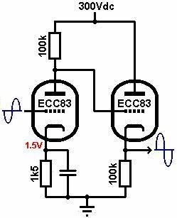
The signal from conversion resistor is tied to the grid.
I'm using 6DJ8 valves, 180V mosfet regulated supply, 8k2/2W anode resistor, 150ohm cathode bias resistor (unbypassed by capacitor) and 15k/2W cathode resistor in the cathode follower.
The picture omits output signal capacitor (at least 0,47uF Mundorf silver in oil or better, that's essential) and resistor (100k or more) from output to ground. Hope this is clear enaugh.
thank you very much for your quick answer
Don't know if I remember well but seems like the tube stage used to invert the phase of the signal so are you using only the L- & R- (since this will be reverted)?
so this would mean that you are using L+ & R+ to GND via the I/V resistor? of what value is this I/V resistor you are using?
I have already a tube output for CS4397 but with 1 x russian 6N6P tube and I also have a similar tube output for TDA1541A using 2 x 6N2P russian tube (a la lampizator design)...do you think that changing these values of components that you gave here might worth a try using that kind of tube only as a quick and dirty solution for the PCM1798 ? (it would be just for a quick comparison and later I would build a separate circuit if it would be worth it soundwise)
Many thanks!
Yes, this tube stage inverts phase, so I take the signal from (-) outputs. But I don't believe in absolute phase, so it's not essential.thank you very much for your quick answer
Don't know if I remember well but seems like the tube stage used to invert the phase of the signal so are you using only the L- & R- (since this will be reverted)?
yesso this would mean that you are using L+ & R+ to GND via the I/V resistor?
It depends on gain of the following stage. In this case ~120ohms will do.of what value is this I/V resistor you are using?
CS4397 is voltage output DAC, if you use lampizator style gainstage you get about 20V signal level at output. It's too much for solid state amplifiers and it may lead to damage.I have already a tube output for CS4397 but with 1 x russian 6N6P tube and I also have a similar tube output for TDA1541A using 2 x 6N2P russian tube (a la lampizator design)...do you think that changing these values of components that you gave here might worth a try using that kind of tube only as a quick and dirty solution for the PCM1798 ?
You can try this stage to PCM1798, maybe you will have to change IV resistors value due to different gain of the stage.
The 6N2P tube has very huge internal resistance so you will have big output resistance of the stage. It may lead to weak sound with most of solid state amps and some of tube amps.
Improper gainstage may lead to poor sound and you may never know how great PCM1798 can sound.(it would be just for a quick comparison and later I would build a separate circuit if it would be worth it soundwise)
Many thanks!
I do not appreciate soviet tubes (maybe excluding 6S4S and GM70 with copper anode) and always make efforts to substitute them by western ones.
My budget is what is needed for a top dac, I think this Hegel D25 might be a good bet. Price is 2000 euro.
Hegel Music Systems - HD25
I do want to buy a ready to play unit, not DIY.
Hegel Music Systems - HD25
I do want to buy a ready to play unit, not DIY.
I think there is rather small chance to buy a really top class DAC at this price. Very good one - maybe, but not really top class.
And (thanks to knowledge from this and similar places on the web) one can quite easily build from scratch a really top class DAC at a fraction of that amount. Including really pretty enclosure.
That's my opinion.
And (thanks to knowledge from this and similar places on the web) one can quite easily build from scratch a really top class DAC at a fraction of that amount. Including really pretty enclosure.
That's my opinion.
Hi McGyver,
I just found a pdf file from lampizator site with an alternative schematic of a tube output for PCM1798 it uses some small miniature tube 6N16P and the component values are like in the picture, did you happen to try out this kind of tube output in the past ?
regarding your advice, I found an earlier schematic posted also by you, so one more question, your actual implementation uses that I/V resistor from both phases like in this drawing or just from a single phase and the other is floating? thanks
I just found a pdf file from lampizator site with an alternative schematic of a tube output for PCM1798 it uses some small miniature tube 6N16P and the component values are like in the picture, did you happen to try out this kind of tube output in the past ?
An externally hosted image should be here but it was not working when we last tested it.
regarding your advice, I found an earlier schematic posted also by you, so one more question, your actual implementation uses that I/V resistor from both phases like in this drawing or just from a single phase and the other is floating? thanks
An externally hosted image should be here but it was not working when we last tested it.
Yes, I tried SRPP configuration, but with other tubes, not 6N16B. And the circuit with common cathode followed by cathode follower sounds better in my system.
My earlier schematic needs a lot of effort with finding right values in cathode and IMHO gives no advantage in sound quality in comparison to circuit feeded from single phase only. So I considered why to bother?
My earlier schematic needs a lot of effort with finding right values in cathode and IMHO gives no advantage in sound quality in comparison to circuit feeded from single phase only. So I considered why to bother?
- Status
- This old topic is closed. If you want to reopen this topic, contact a moderator using the "Report Post" button.
- Home
- Source & Line
- Digital Line Level
- Cheapest top dac?