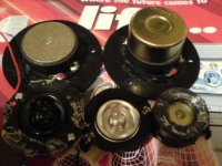
tweeters
Clockwise from top left.
1. The Ariston tweeter pursuaded into the MicroLab tweeter front plate.
2. Looks more impressive with the screening can added.
3. No amount of brute force or ignorance could seperate the bucking magnet.
4. Riesen car driver tweeter. Can clean teeth at 2.5Khz. Limp above 10Khz.
5. The other original MicroLab tweeter.
") /sreten.
/sreten.
Clockwise from top left.
1. The Ariston tweeter pursuaded into the MicroLab tweeter front plate.
2. Looks more impressive with the screening can added.
3. No amount of brute force or ignorance could seperate the bucking magnet.
4. Riesen car driver tweeter. Can clean teeth at 2.5Khz. Limp above 10Khz.
5. The other original MicroLab tweeter.
/sreten.Attachments
Audax tweeters
Falcon Acoustics have 2 of the "proper" 74mm diameter Audax tweeters.
They are £21.50 a pair including P&P.
Having dissected a pair of Audax polydomes and the ML pair I can
confirm the Audax is technically superior, the main difference being
the Audax has a formerless edgewound aluminium voicecoil which
is lighter than the copies copper voicecoil on an aluminium former
glued with appears to be epoxy to the poly dome.
/sreten.
Falcon Acoustics have 2 of the "proper" 74mm diameter Audax tweeters.
They are £21.50 a pair including P&P.
Having dissected a pair of Audax polydomes and the ML pair I can
confirm the Audax is technically superior, the main difference being
the Audax has a formerless edgewound aluminium voicecoil which
is lighter than the copies copper voicecoil on an aluminium former
glued with appears to be epoxy to the poly dome.
/sreten.richie00boy said:What model are the Audax tweeters that Falcon have?
TW010F1
http://www.falcon-acoustics.co.uk/pl28p10.htm
http://www.falcon-acoustics.co.uk/TW010F1a.jpg
http://www.falcon-acoustics.co.uk/TW010F1b.jpg
/sreten.consort_ee_um said:
The amplifiers look like clones of the TDA2030A which is a SGS/Thomson design but it has someone else's logo
The tweeter capacitor is 2.2uF
I measured the rails +/- 20V.
This should give ~ 30W into 4ohms - huh ? lot more than specified 13W.
/sreten.Hi Sreten
The transformer is only rated at ~25VA so when the speakers are drawing an amp, say the voltages will go down a lot, by as much as 6 to 8V. If you want to power an op amp (for your parametric EQ) with regulators like the 78L15 and 79L15 the voltage could drop below the requirement for regulation. I would use 78L12 and 79L12 but even with those the op amp supply may drop out of regulation, if you like your music loud! Modern TI op amps will work off +/-22V supplies and you could use those unregulated -bearing in mind this is a cheap project
The transformer is only rated at ~25VA so when the speakers are drawing an amp, say the voltages will go down a lot, by as much as 6 to 8V. If you want to power an op amp (for your parametric EQ) with regulators like the 78L15 and 79L15 the voltage could drop below the requirement for regulation. I would use 78L12 and 79L12 but even with those the op amp supply may drop out of regulation, if you like your music loud! Modern TI op amps will work off +/-22V supplies and you could use those unregulated -bearing in mind this is a cheap project
I've used a few of those classic budget Audax's in the past on a few projects. I have a soft spot for them as they were the first proper tweeters I bought They aren't too bad considering. I used to get them from Maplin for £6.99 each, before they decided it was more profitable to sell computer modding cack and employ monkeys.
Whilst probably a fair bit lower down the band than you want to go, I have run them with 4.7uF + 3.3 ohms in series as a rudimentary crossover and never blew them up, and sound was respectable enough.
They aren't too bad considering. I used to get them from Maplin for £6.99 each, before they decided it was more profitable to sell computer modding cack and employ monkeys.Whilst probably a fair bit lower down the band than you want to go, I have run them with 4.7uF + 3.3 ohms in series as a rudimentary crossover and never blew them up, and sound was respectable enough.
consort_ee_um said:Hi Sreten
The transformer is only rated at ~25VA
Thanks, I wasn't sure of the VA rating.
I plan to add an extra 2 2,220uF capacitors low impedance switching types.
The continuous rating is fairly academic - it is good with the voltage
rails as they are the amplifiers should manage around 30W unclipped
transients - and thats what counts most of the time.
/sreten.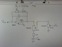
I have done some investigation of the amp.
It has 37dB of gain- rather high for a TDA2030 but since it is the only active gain element it has to compensate for the loss of the passive tone controls.
It slightly concerned me that there were no fuses in the design but what they have done is put a 0.5 ohm resistor in series with the speaker output. I think this is a safety device, which will open circuit if a severe fault like shorting the output happens. You can get special fusible resistors for this application.
Of course this puts the Qts up, not what is wanted as it will slightly increase the boominess and it will also lower the power output.
consort_ee_um said:It slightly concerned me that there were no fuses in the design but what they have done is put a 0.5 ohm resistor in series with the speaker output. I think this is a safety device, which will open circuit if a severe fault like shorting the output happens. You can get special fusible resistors for this application.
Of course this puts the Qts up, not what is wanted as it will slightly increase the boominess and it will also lower the power output.
Hi,
Qts goes up from 0.81 to 0.89 with the additional 0.5R.
I'm fairly sure the purpose of the resistor is to replace the standard
output inductor (and capacitor zobel ?). The inductor should have a
damping resistor anyway so it may be just a question of parts count.
According to D.Self 0.22R is usually enough to allow omission of
the inductor, so the 0.5R resistor could be paralleled with another.
Qts would then be 0.83 - a fairly minimal change from 0.81 .
/sreten.Hi VK,
I've lost some enthusiasm for them since I realised the basic midrange
is not too hot andthere is not much that can be done about it.
I've been struggling with the passive preamp to get a set up that
requires a reasonsable inductor value. As I'm driving them from a
portable CD player changing the input pot to 100R helps but try
getting a dual gang 100R potentiometer.
I may leave the preamp as it is - need to sort out the drivers c/o.
/sreten.
I've lost some enthusiasm for them since I realised the basic midrange
is not too hot andthere is not much that can be done about it.
I've been struggling with the passive preamp to get a set up that
requires a reasonsable inductor value. As I'm driving them from a
portable CD player changing the input pot to 100R helps but try
getting a dual gang 100R potentiometer.
I may leave the preamp as it is - need to sort out the drivers c/o.
/sreten.Hi all,
I've designed a first attempt at a 2nd order (electrical) crossover.
However the midbass low pass section proved to be very sensitive
to the inductance of the bass unit (unlike the treble section).
I'm unsure of the scaling of VK's impedance graph.
My rough attempts at estimating Le give around 200uH,
surely this is too low ?
Methinks the 10R line is very misleading,
surely the bass unit low frequency impedance peaks would exceed this ?
/sreten.
I've designed a first attempt at a 2nd order (electrical) crossover.
However the midbass low pass section proved to be very sensitive
to the inductance of the bass unit (unlike the treble section).
I'm unsure of the scaling of VK's impedance graph.
My rough attempts at estimating Le give around 200uH,
surely this is too low ?
Methinks the 10R line is very misleading,
surely the bass unit low frequency impedance peaks would exceed this ?
/sreten.Vikash said:I'll take the measurements just to make sure...
Hi,
could you send me the SW file you've already measured ?
/sreten.I used Unibox to see what bass response I would get with a lower Qts and it gave a nice flat response with Qes = 0.55 which is half the value Vikash measured.
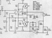
I had an old Consort amp. with negative output resistance kicking around so I thought I would try modding it to give a negative resistance of 1.7 ohm, again half the coil resistance Vikash measured. This in theory would give a Qes of 0.55. To do this I modified these values in the schematic below
R29 1k
R30 0.11
R31 0.11
R13 9k1
C10 4.7N
C22 4.7N
I also used a sallen & key high pass filter with a 51Hz cutoff using 0.22u caps & 10k & 20k resistors. This limits the cone excursion when the speaker is not producing any noticeable output.
Result - stunning bass considering the 5 litre size of the speaker.
Its so impressive I plan to implement this on a thin strip of veroboard and attach it to the main amplifier board.
1) Beef up the supply using 1N4004 diodes in parallel with the existing bridge diodes and substitute 4700uF reservoir caps for the standard 2200uF
2) Wire out the passive tone controls
3) Use existing TDA2030s with extra circuits using dual high voltage op amps which will take +/-22V. One channel for the high pass filter and the other for the current feedback amp.
Could use either TLE2142 or MC33172 op amps for this.
Will let you know how this goes.
Thanks to Sreten for the original tip and Vikash for the measurements.
Attachments
- Status
- This old topic is closed. If you want to reopen this topic, contact a moderator using the "Report Post" button.
- Home
- Loudspeakers
- Multi-Way
- cheap project in the UK