Hi,
Not Dave but...
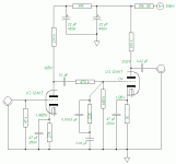
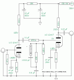
Changing the B+ to 200VDC iso 250VDC would require a total redesign of the phonostage; not just the load and bias resistors would have to be changed but the entire RIAA correction circuit as well.
There's absolutely nothing to be gained by doing so IMHO.
Cheers,
Can I use a B+ of 200V on the RCA phono circuit? If not, can I change any of the resistors to so that I can use it for the 200V B+ I have?
Not Dave but...
Changing the B+ to 200VDC iso 250VDC would require a total redesign of the phonostage; not just the load and bias resistors would have to be changed but the entire RIAA correction circuit as well.
There's absolutely nothing to be gained by doing so IMHO.
Cheers,
While I agree with Frank,...if I had to choose, I''d let your B+ fall where it may. Changing your load resistor to meet your B+ requirement will totally screw your riaa network. Letting your B+ fall where it may would only effect your tube's linearity.
I'd rather have a linear riaa, with some distortion, than a distorted riaa being cleanly reproduced.
Does that make sense?
I'd rather have a linear riaa, with some distortion, than a distorted riaa being cleanly reproduced.
Does that make sense?

Hi,
Unfortunately, if you follow your own advice in this particular case, I can garantee you will have both problems at once.
To me it does...
Cheers,
I'd rather have a linear riaa, with some distortion, than a distorted riaa being cleanly reproduced.
Unfortunately, if you follow your own advice in this particular case, I can garantee you will have both problems at once.
Does that make sense?
To me it does...
Cheers,
Here's the circuit with RIAA pre in my Stereo Contol Centre. It uses NFB, so it's *very* quiet 
http://www3.telus.net/small_business/Geek/tubeCtrlCtr.png
What isn't shown is DC regulated heater, bypassed through 10uF capacitor to chassis ground and the +250 volt SS regulator.
http://www3.telus.net/small_business/Geek/tubeCtrlCtr.png
What isn't shown is DC regulated heater, bypassed through 10uF capacitor to chassis ground and the +250 volt SS regulator.
Yes! http://www.turneraudio.com.au has some fabulous passive RIAA circuits. They sound great and would use them in a standalone box in a minute.
My decision was based on personal preference. I built both side by each on a breadboard and did listening comparisons. I liked the active version for its mellow sound and at the time I built it (for transferring my vynil to PC), it could drive the soundcard input directly without buffering. NFB by nature reduces the output impedance to much lower levels making them less immune to loads.
My decision was based on personal preference. I built both side by each on a breadboard and did listening comparisons. I liked the active version for its mellow sound and at the time I built it (for transferring my vynil to PC), it could drive the soundcard input directly without buffering. NFB by nature reduces the output impedance to much lower levels making them less immune to loads.
arnoldc said:jojo, i'd use 1 watter too unless you have a problem with space.
kabayan arnoldc,
Thanks for the quick response. Since it would be a prototype circuit in p2p wiring, I don't think that space would be a problem. I'll follow your advice then, will be buying parts today so your post is in perfect timing. Thanks man!
Hi,
In case you can't find all the reistors in 1W form: all the others can be 1/2W. (Plate and cathode, gridleak can be 1/4W)
Make sure to match the resistors L+R channel for the RIAA curve, best to order 1% values if possible.
If you want to implement the fourth time constant of the RIAA correction get yourself a pair of 953R and 12R1 1/4W 1% resistors.
Cheers,
I'll follow your advice then, will be buying parts today so your post is in perfect timing.
In case you can't find all the reistors in 1W form: all the others can be 1/2W. (Plate and cathode, gridleak can be 1/4W)
Make sure to match the resistors L+R channel for the RIAA curve, best to order 1% values if possible.
If you want to implement the fourth time constant of the RIAA correction get yourself a pair of 953R and 12R1 1/4W 1% resistors.
Cheers,
Attachments
Why would you bother with a PCB for a schem this simple? Point-to-point it snouldn't take maore than an hour or so for both channels, and costs $0 extra above the parts cost.arnoldc said:jojo, can you make a dual mono PCB and i'll buy a pair from you?
arnoldc said:jojo, can you make a dual mono PCB and i'll buy a pair from you?
i can as soon as I finished a prototype.
fdegrove said:Hi,
In case you can't find all the reistors in 1W form: all the others can be 1/2W. (Plate and cathode, gridleak can be 1/4W)
Make sure to match the resistors L+R channel for the RIAA curve, best to order 1% values if possible.
If you want to implement the fourth time constant of the RIAA correction get yourself a pair of 953R and 12R1 1/4W 1% resistors.
Cheers,
Fortunately I found all the resistors. Since they came cheap I bought 20 pcs per value so I can match them.
Doesn't the original RIAA have a 50KHz rolloff? If it would improve the sound then I'll include it since It's pretty easy to implement. But must it be 953R and 12.1R exactly?
Thanks Frank!
Hi,
Have a look at Mr. Allen Wright's paper about this here:
RIAA
That's as close as I could get to the calculated value, 963R IIRC.
You could use a single 1K resistor per channel just to see if you like what it does.
You're welcome,
Doesn't the original RIAA have a 50KHz rolloff?
Have a look at Mr. Allen Wright's paper about this here:
RIAA
But must it be 953R and 12.1R exactly?
That's as close as I could get to the calculated value, 963R IIRC.
You could use a single 1K resistor per channel just to see if you like what it does.
You're welcome,
Hi,
Should have read 965R. Typo.
BTW, regarding PCBs, it's really worth a try to make two identical preamps except for one with PCB, the other P2P and compare the two.
You're in for a big surprise I promise.
Since you're two persons building, why not do one each?
Afterwards you can combine different values to arrive at the calculated value of 965R, I just picked the easiest two at the time out of the E96 table.
Cheers,
That's as close as I could get to the calculated value, 963R IIRC.
Should have read 965R. Typo.
BTW, regarding PCBs, it's really worth a try to make two identical preamps except for one with PCB, the other P2P and compare the two.
You're in for a big surprise I promise.
Since you're two persons building, why not do one each?
I'll probably use a single 1K resistor for the RIAA correction, I have a lot of 1K resistors and so can be matched.
Afterwards you can combine different values to arrive at the calculated value of 965R, I just picked the easiest two at the time out of the E96 table.
Cheers,
- Status
- This old topic is closed. If you want to reopen this topic, contact a moderator using the "Report Post" button.
- Home
- Amplifiers
- Tubes / Valves
- Cheap and Easy Tube Phono Preamp


