Hi guys, after search the forum i really cant find an cheap soft start to build. Im building an 500Wx2 Power Amplifier, i really want to use an soft start to charge the capacitors.
Can someone please point me to some simple design of that? some IC that help me to that?
Thank in advance
Can someone please point me to some simple design of that? some IC that help me to that?
Thank in advance
Use the advanced search function and search on titles only. There are lots of threads on soft starts. diyAudio - Search Results
The easiest one of all is a CL-60 in series with the transformer primaries. A couple of bucks and you're done.
The easiest one of all is a CL-60 in series with the transformer primaries. A couple of bucks and you're done.
Hi guys, after search the forum i really cant find an cheap soft start to build. Im building an 500Wx2 Power Amplifier, i really want to use an soft start to charge the capacitors.
Can someone please point me to some simple design of that? some IC that help me to that?
Thank in advance
The simplest and cheapest is a switch and a power resistor.
Once powered up the switch shorts out the resistor.
Otherwise it will be relays and delay timer.
Personally I try to avoid them as I have seen so many threads where the soft start has caused a problem.
I run a 1000VA transformer with no soft start just a 13 ampo mains fuse.
Sam,
For the sake of safety, I strongly suggest not just upping the fuse until it stops blowing on turn on. Nigel's fuse allows an extreme overload of the transformer (2800+VA) without blowing the fuse. That's fine for Nigel as long as he is comfortable with it, but I don't believe that it is good practice.
A CL-60 will limit the inrush, heat up and be almost transparent. It will not protect against inrush if the amp is cycled off and back on before it has a chance to cool. To me that is a small price to pay for no moving parts reliability.
Some would suggest an improvement in sound quality using a switch or relay to bypass the CL-60 after start and allow it to cool and be ready to protect a rapid cycle. My amps that use them do not have this feature and I haven't felt a need to investigate whether that would improve the sound quality. I use a CL-30 and a 6A slow blow fuse on my amps with 1KVA transformers
I use 20 Ohm/12W high temp resistor and a relay powered from DC output. As soon as all voltages are proportionally up the relay shorts the resistor up.
It will protect from inrush when cycled on/off: if relay is still on that means capacitors are charged, so no inrush current. If they are discharged, the relay is off. However, on/off voltages for relay are different, but it is not a big deal, according to my experience.
It will protect from inrush when cycled on/off: if relay is still on that means capacitors are charged, so no inrush current. If they are discharged, the relay is off. However, on/off voltages for relay are different, but it is not a big deal, according to my experience.
I use one of these ...
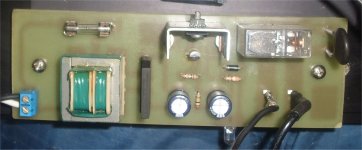
15A NTC thermistor , as current passes through resistance goes down to 2-3R. Circuit below, ( magnetron relay - 20A and 12.8V trafo from broken micro oven) triggers relay across the thermistor after 3 seconds.
All junk parts , has lasted for 3 months now to keep inrush from 1KVA trafo at bay.
OS
An externally hosted image should be here but it was not working when we last tested it.
15A NTC thermistor , as current passes through resistance goes down to 2-3R. Circuit below, ( magnetron relay - 20A and 12.8V trafo from broken micro oven) triggers relay across the thermistor after 3 seconds.
All junk parts , has lasted for 3 months now to keep inrush from 1KVA trafo at bay.
OS
Attachments
A CL-60 is not the best choice without a relay bypass.
CL-60
Manufacturer: GE Sensing / Thermometrics
Description: Thermistors - NTC 5 Amps 10 Ohm
The resistance is too high, and the current rating is not high enough. I have had a CL-60 blow to pieces from the inrush current of a Hafler DH500.
For a 500W x2 amplifier I would choose a device between 1R0~2R5 with a current rating of 15A~20A.
Digi-Key - 570-1041-ND (Manufacturer - SL22 1R020)
Digi-Key - 570-1047-ND (Manufacturer - SL22 2R515)
Digi-Key - 570-1044-ND (Manufacturer - SL22 2R018)
one CL60 does not have the capacity to soft start a large toroid.
Use two CL60.
On 220/240Vac use a pair in series to feed the 230Vac transformer.
On 110/120Vac use one in each primary feed of a dual 115Vac primary transformer.
Correctly selected NTC are better than Power Resistors. But I find that it is much cheaper to use a stack of 5W resistor than a pair of CL60 for each transformer. The resistors are good enough.
Both NTC and resistor soft-starts benefit from a relay bypass as soon as the transformer has turned on.
Slow charging of a capacitor bank is completely different.
The best location for a slow charge circuit is in the secondary between the transformer and the capacitor bank. Again the slow charge NTC or resistors need to be bypassed when the caps are near full charge.
Hello Samsagaz,
I have just etched these PCBs:
following this schematic:
My old laptop-PSU's output (15VDC /2.5A) is fed to a 12V 7812 voltage regulator. The 7812 voltage regulator will then activate relay K1, which passes the main's voltage (220V) via 2 NTCs (22 Ohm each, thus delimiting the inrush current to approx. 5A) to the main's output connector.
The 7812 voltage regulator's output will also trigger a LM555 timer (via R1/C1).
The output of the LM555 feeds relay K2, which will bypass the NTCs after the pre-defined time (aprox. 0.8 sec).
I will solder this little PCB (70 x 70 mm) and test it over the weekend.
If it works (and you like it and you have a wallboard-PSU), you can have my spare PCB.
Best regards - Rudi_Ratlos
I have just etched these PCBs:
An externally hosted image should be here but it was not working when we last tested it.
An externally hosted image should be here but it was not working when we last tested it.
following this schematic:
An externally hosted image should be here but it was not working when we last tested it.
My old laptop-PSU's output (15VDC /2.5A) is fed to a 12V 7812 voltage regulator. The 7812 voltage regulator will then activate relay K1, which passes the main's voltage (220V) via 2 NTCs (22 Ohm each, thus delimiting the inrush current to approx. 5A) to the main's output connector.
The 7812 voltage regulator's output will also trigger a LM555 timer (via R1/C1).
The output of the LM555 feeds relay K2, which will bypass the NTCs after the pre-defined time (aprox. 0.8 sec).
I will solder this little PCB (70 x 70 mm) and test it over the weekend.
If it works (and you like it and you have a wallboard-PSU), you can have my spare PCB.
Best regards - Rudi_Ratlos
Hello Samsagaz,
I have just etched these PCBs:
1. Those pics are TOO big.

2. Your line voltage (mains) is too close to the low voltage side on the board. You need to account for creepage clearance for the space between these traces.
The best location for a slow charge circuit is in the secondary between the transformer and the capacitor bank.
No.
When resistor is in primary time constant depends on it's value and all capacitors in all rectifiers reflected to the primary. All filter capacitors are charged slowly, the resulting time is defined by most current hungry one, if one exists, otherwise all inrush currents are proportionally limited. However, if you have only one rectifier, it does not matter theoretically, it is just your own decision: either limit ten amp in primary, or hundred amps in secondary.
Last edited:
Hi,
I do not agree with your no.
Yes you can put a pair of CL60 in the primary circuit and yes they will slow down the charging of the smoothing bank.
But, I assert that the better location for a slow charge control is in the secondary circuit.
Why do I assert that? Because it's the recommended layout in the manufacturers' datasheets.
Last edited:
"Oha" (German expression for surprise), MJL21193,
you just tell from a short glance: "Won't work."
The nearest distance between the main's voltage and any signal wire is 15mm.
Let me please check this weekend, if it works.
I also think, that you would never approve a PCB like this one:
This PCB, drawn with MS Paint by me, playing flawlessly since many months, belongs to one of best ampilfiers, I have ever listened to.
Those, who know me, know of course, which it is.
There is a big gap between theory and practical experience.
Are you aware of it?
Best regards - Rudi_Ratlos
you just tell from a short glance: "Won't work."
An externally hosted image should be here but it was not working when we last tested it.
The nearest distance between the main's voltage and any signal wire is 15mm.
Let me please check this weekend, if it works.
I also think, that you would never approve a PCB like this one:
An externally hosted image should be here but it was not working when we last tested it.
This PCB, drawn with MS Paint by me, playing flawlessly since many months, belongs to one of best ampilfiers, I have ever listened to.
Those, who know me, know of course, which it is.
There is a big gap between theory and practical experience.
Are you aware of it?
Best regards - Rudi_Ratlos
Rudi, the issue is safety not function. In your picture above, the trace that the "mm" of your dimension falls on is a low voltage trace. There really isn't a reason for it to be so big since it doesn't carry a lot of current. Reduce its width to allow more space between it and the mains connection. I'd grind a bite out of it on your current board.
Others with more experience can tell you how much space is needed.
Others with more experience can tell you how much space is needed.
"Oha" (German expression for surprise), MJL21193,
you just tell from a short glance: "Won't work."
Like BobEllis said above, the issue is safety.
Just trying to be helpful.
- Status
- This old topic is closed. If you want to reopen this topic, contact a moderator using the "Report Post" button.
- Home
- Amplifiers
- Solid State
- Cheap and Easy Soft Start?