Trebla said:Thanks Andrew.
Sounds like the transformers' low inductance could be the root of the problem.
13H seems low for 5K.
As for the rest of it. A rebuild into a bigger box would help but then it's not such a cheap amp by the time you've finished.
Its a shame these are so compromised. A few more dollars spent in the right areas would make it a much better proposition.
However, there's always the chance that the bass might improve with time.
I dont think there were a few dollars more...
Really it was bought to play with. Putting the electrics into a bigger box is not too much of a bind (the internal wiring except for the trafo's, is a subassembly - lucky...
I agree about the transformers though and I've sort of come to the conclusion that they're next. - time to go bargain hunting...
By the way I'm talking here about one particular amp, I'll say it again that the Yarland and Bada examples I've had are/were great, particularly at the price.
Andy
Re: Re: experimentation?!?
Sorry, I wasnt sure myself... It stems from a (less than) half remembered article about where the volume pot would ideally be sited. (when I think about it, it probably had something to to with the RC of the input wiring and tube)
Anyway I bunged in the 250K and had no problems
Andy
poynton said:
HI.
What do you mean by this ??
Andy (yes,another one!)
Sorry, I wasnt sure myself... It stems from a (less than) half remembered article about where the volume pot would ideally be sited. (when I think about it, it probably had something to to with the RC of the input wiring and tube)
Anyway I bunged in the 250K and had no problems
Andy
....and another thing
Back home for a couple of weeks, So a little update incase anyones looking at these on Ebay...
Changed the power tubes for EL34's and Its made a distinct improvement! (JJ E34L's actually)
Maybe its the reduction in standing current but it seems to have helped the response, or maybe its that they are "better" tubes.
Whatever, its an easy mod. Biased up at a reasonable point without any assistance, I just switched the tubes
Andy
...and finally
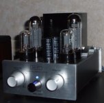
For the record this is the amp as it stands now - I'm pretty happy with it, Done all the tweaky bits I plan to for the time being.
A couple of points
- finally it has some bass infact its reasonably flat down to 30Hz
- KT88 tubes are in storage - I'm sticking with the E34L's (in triode mode)
- it now doesnt get quite so HOT...
Andy
Attachments
Frequency response,
Measured with sine wave from a laptop and checking the amplitude at the speaker terminals on the 'scope.
Amp driving speakers not a dummy load and not at full output (about 50% volume)
Note the relative amplitude between the triode and UL modes, they are not scaled.
Wish I'd also done this before adding the feedback but nevermind...
Andy
Attachments
ahhhh BOTHER...
Yes I see your point. This is what happens when you tack the feedback on at the end... Thanks for pointing it out though I might never have noticed it
A corrected frequency response is attached!! - more like I was expecting.
My mistake raises an interesting dilemma though. With the cap in place the response is less linear but the hump at 100 Hz subjectively gives more (better) bass response - The shunting affect of the cap decresing at LF I suppose...
I guess this isn't as finished as I thought.
Andy
Attachments
Feedback has a large impact on the damping factor. I've seen sub-1 damping factors on some builds when using UL without it. You'll certainly get more subjective bass with such a low DF but as your graphs confirm more true deep bass with feedback.
BTW, have you considered a small, say 0.22uF, film cap instead of the 22uF (electrolytic?) shown in the coupling position?
Edit: You might also want to consider a larger cathode bypass on the output tube. The corner frequency shown is pretty high.
BTW, have you considered a small, say 0.22uF, film cap instead of the 22uF (electrolytic?) shown in the coupling position?
Edit: You might also want to consider a larger cathode bypass on the output tube. The corner frequency shown is pretty high.
I see the switch on the output trafo, and was considering doing similar, in that respect and also in certain power supplies where I would need to cut on/off the HV only and not the filament secondaries.
Almost all toggle switches I've seen are not rated over 250v, I'm just wondering if it's fairly safe to use them this way (perhaps switching 450v or so and low amperages 150-200 ma) and not run into a problem where it would create a hazard at some point. Or do you need a special switch?
I generally use new manufacture 10A/277VAC toggles, but some of the antique C-H & Arrow are only rated at 3a and use multi wafer plastic.
rdf said:Feedback has a large impact on the damping factor. I've seen sub-1 damping factors on some builds when using UL without it. You'll certainly get more subjective bass with such a low DF but as your graphs confirm more true deep bass with feedback.
BTW, have you considered a small, say 0.22uF, film cap instead of the 22uF (electrolytic?) shown in the coupling position?
Edit: You might also want to consider a larger cathode bypass on the output tube. The corner frequency shown is pretty high.
Both the plots have feedback - the second lot DONT have the 220uF shuntng most of it to ground.
I'm going to do some more tests today With 8 ohm dummy loads, at full amplitude with / without feedback and with KT88 vs EL34
As for the cap value - that will be the subject of some moral debate. I have misgivings about using a cap to boost bass. I dont know if i feel its valid to "fix" it in that way. (note, I have no problem with adding gobs of feeedback
") )
) The 220uF value was fitted before the amp had F/B as a cathode bypass
I had trouble with the sizing cap on the output stage I reckoned to need something like 768uF which, 1: I didn't have and 2: wouldn't fit in the chassis. In fact it has a 220uF/100v fitted at the moment. the 47uF was as delivered.
Now theres a thought! if I remove it I'll lose some power (right?) but the local feedback will affect all frequencies equally - could be a reasonable trade.
Andy
frank754 said:I see the switch on the output trafo, and was considering doing similar, in that respect and also in certain power supplies where I would need to cut on/off the HV only and not the filament secondaries.
You should to turn off the HT before switching, theres a big THUD at the speakers if you dont..

I just straight forward turn the amp off. The switch is nothing special. Just a 2 position rotary, I could be wrong (and lucky) but I don't think theres ever that much voltage across it - The screen is at 300 odd volts either way. (I see it as switching between 336v and 313v)
The insulation between you and that is different from the switching capacity. If you actually want to switch 450v ON then youre going to get a pretty good arc with a 240v contact (you get a pretty good arc when switching 250 to be honest)
Not that I suggest that you completely ignore the specs but I reckon the 250v rating is a legal standard. You're right EVERYTHING is rated like that.
Andy
The results
Makes interesting reading - Yes in this application the KT88 puts out less voltage because of its lower mu but I'm theorising that the LF roll off is due to the higher quiescent current through the transformer. 96mA instead of 76mA with the EL34.
Is that a reasonable assumption? Whilst I'm making excuses For the KT88 - Ri is 670ohms (triode) vs 910 for the EL34 I guess that the 5k plate resistance here is a bit better for the EL34 too
May also be worth pointing out that the feedback reduced the gain of the first stage from 10 (without that cathode bypass) to 5.
Which I THINK implies 6dB of feedback? Is that correct?
Incidentally - without feedback hum is now 20mV dont know what I did there...
Andy
Attachments
Re: ...and finally
On the off chance that RDF reads this THANKS!
as it turns out I wasn't happy with it
So as a result of some judicious tweaking - feedback resistor is 18K now
Finally upped the cathode bypass on the Output Stage to 1000Uf with some pretty cheeky wiring...
NO cathode bypass on the input stage or caps in the feedback loop I tried various sizes to try and massage the frequency response - it didnt really help any before I ran out of patience.
SO. realistically I got this amp for £90 and apart from the change of input tube (about 80% beacuse I like the 6j5) I've added a feedback loop, a triode option, and increased the bypass cap on the output stage. (which is now EL34 not KT88) maybe another £2 before the output tube change (my E34L's cost £26 for a matched pair from voc_rock on ebay)
Well I know I've said it before, but I'm pretty happy now...
(OK there's room for improvement - but not in that diddy box)
Andy
andrew_whitham said:For the record this is the amp as it stands now - I'm pretty happy with it, Done all the tweaky bits I plan to for the time being.
On the off chance that RDF reads this THANKS!
as it turns out I wasn't happy with it
So as a result of some judicious tweaking - feedback resistor is 18K now
Finally upped the cathode bypass on the Output Stage to 1000Uf
with some pretty cheeky wiring... NO cathode bypass on the input stage or caps in the feedback loop I tried various sizes to try and massage the frequency response - it didnt really help any before I ran out of patience.
SO. realistically I got this amp for £90 and apart from the change of input tube (about 80% beacuse I like the 6j5) I've added a feedback loop, a triode option, and increased the bypass cap on the output stage. (which is now EL34 not KT88) maybe another £2 before the output tube change (my E34L's cost £26 for a matched pair from voc_rock on ebay)
Well I know I've said it before, but I'm pretty happy now...
(OK there's room for improvement - but not in that diddy box)
Andy
Hi, Andy.
I bought one of these amps too, and plan to modify and experiment - mostly to learn about tube amplifiers. (This is my first - though I have made many SS amps).
I have bareley powered up mine. I have quite a pronounced hum, which I must get rid of first.
How is your modifications going? What is the status now? Do you have a schematic?
Espen
EspenE said:Hi, Andy.
I bought one of these amps too, and plan to modify and experiment - mostly to learn about tube amplifiers. (This is my first - though I have made many SS amps).
I have bareley powered up mine. I have quite a pronounced hum, which I must get rid of first.
How is your modifications going? What is the status now? Do you have a schematic?
Espen
excellent, well you can certainly improve on it as it comes...
Note since you say this is your first tube amp please be careful with the voltages. Just because the 'petite' nature of the case makes it really easy to short something out - I came close on a couple of occasions.
First thing to do is DUMP the headphone circuit. I got the humm to acceptable levels then - its still not silent but... well, I was amazed at the difference.
If you still arent happy with it, and my speakers are only 90db so Humm is less than an all encompassing issue. I'd suggest splitting the filtering in the PSU into more sections. ie split the 300 ohm resistor into two 150's and add another cap (you might fit it in between the trafo's inside the unit?)
At which point I have the idea to drill some holes in the case... I havent but I might.
The circuit I stopped on is as post 24 but without that coupling cap on the input tube - doesnt work just leave it out.
Cathode bypass on the output tube is 1000u all the better to get what bass there is available.
And play around with the feedback resistor, I genuinely felt that in this case a little f/b rescued the amp but before I'm sent to SE jail I'll point out that its not for everyone
Same argument for the 6j5's I found the original tubes quite nasty to look at so I determined to change them for less than sound engineering reasons .
Oh and although I installed the triode / UL switch I NEVER use the UL mode, it was fun to play with, but ultimately I wouldnt bother unless you find triode mode hasnt the guts you need.
good luck, I for one, will be interested to learn of your impressions.
Andy
So when do we get to see a picture of the Chinese amp? You mentioned an ebay auction number in the first post four pages ago. I assumed it was long closed and pulled so didn`t bother the trouble to go look. Much trouble since you did not provide a hotlink. I`m lazy that way. No problem.
As for a replacement output xfmer have you hear Tubelab raving about the inexpensive yet impressive Edcor?
As for a replacement output xfmer have you hear Tubelab raving about the inexpensive yet impressive Edcor?
- Status
- This old topic is closed. If you want to reopen this topic, contact a moderator using the "Report Post" button.
- Home
- Amplifiers
- Tubes / Valves
- Cheap and Chinese KT88 SE amp