frequency responce , distortion ,and power was never the queastion on this amplifier
stabilty though and absense of any protection and especialy from its shelf was always the question around those designs
for your information both velleman and smart kit that produces a by far sophisticated kit that is based on the same outputs but also includes proper filtering, Vi limmiter ,and current source for the ltp fails at any sign of "pushing around "
you may find some of the reasons in a post called "a darligton story " here in the forum
Lots of amps have no protection or limiters. I don't believe the original designer ever intended or advertised it. He did include rail fuses that would provide minimal protection.
This thread explicitly said this amp won't work. I built it before I found this thread and my experience was that it did work. I have not seen any stability problem. I've been playing with this design because of its low cost and simplicity and am working on adding protection. You can also buy pre-built or DIY amp kits from China for next to nothing, but that isn't the point.
I am very curious to read the thread you mentioned, but my search for "darlington story" only yields a thread to a post wherein you recommend the thread. A link would be greatly appreciated. Thanks.
check the currents in the two halves of the first LTP and in the second LTP.
You will find that R5, 22k needs massive adjustment to get the emitter currents in the two halves to exactly match.
at the moment first is grossly mismatched.
The second is badly mismatched.
I suspect the improvement in distortion is at least due in part to the slightly improved balance of the LTP.
You will find that R5, 22k needs massive adjustment to get the emitter currents in the two halves to exactly match.
at the moment first is grossly mismatched.
The second is badly mismatched.
I suspect the improvement in distortion is at least due in part to the slightly improved balance of the LTP.
amplifier will work .....to define work in this case will mean that music will come out of it now ... how good or how stable is an other question
here is the thread that talks a bit around the problems with darligtons and why only one ore two comercial amps were made with tip 142 147
http://www.diyaudio.com/forums/solid-state/141780-darling-ton-story.html
here is the thread that talks a bit around the problems with darligtons and why only one ore two comercial amps were made with tip 142 147
http://www.diyaudio.com/forums/solid-state/141780-darling-ton-story.html
You're right about that. Q2 Ie is 0.61ma vs Q1 Ie of 1.4ma. More than a factor of 2.
Thanks for pointing that out. This is probably one of the reasons distortion is so high. I'm working on the son of Cheap150. I call it the SOC150. At least it has the LTP problem fixed. I'm sure it will still have a long list of other problems.
Thanks for pointing that out. This is probably one of the reasons distortion is so high. I'm working on the son of Cheap150. I call it the SOC150. At least it has the LTP problem fixed. I'm sure it will still have a long list of other problems.
even this circuit http://www.quasarelectronics.com/images/smart-kit/1077d.pdf that is actually the most sophsticated circuit that was ever made around those still ...wasnt stable enough due to the nature of darligtons as described in the thread
only in Greece that smart kits managed to sell around 1000-1500 kits of those none of them works till today ...
( probably if one uses high quality material , proper miller caps , better input filtering might become more stable ) but then what's the catch ??? we have so many nice amps working around her with none of the above problems
Last edited:
What many people fail to realise that this amplifier is not meant to be HiFi (whatever that means) but was built - I hesitate to say designed - as a guitar amplifier. Low distortion was not a priority, and so long as it amplified the limited frequencies of a guitar into a guitar speaker - most are 3dB down at 5KHz - John Fisher was satisfied. All amplification was at high volume so crossover distortion was not a problem - most noticeable at low volumes. Also the little that was noticed would only add colouration to the guitar sound.
That amp your linked to looks like an old TI design. I've seen it before. Don't know if that's the most sophisticated design, though. STmicro had a nice one using their TDA7250 chip. And how about National's LME49811 design? It's a little newer. So the Darlington isn't dead yet... in spite of your best efforts. 
I thumbed through that Darlin...ton thread and found it interesting. But there is a lot of opinion and conjecture there. I can't help but take it with a grain of salt. I've read before that darlingtons don't measure as well as discretes, and I believe that. You make a good point that the value of the Rs used inside darlington packages varies between manufacturers, so it becomes a little more difficult to model the circuit. Here in the US we still have some good reliable distributors who can consistently deliver name brand parts at reasonable prices. So counterfit parts are not a huge problem unless maybe if you're shopping on ebay from China.
Using high quality and expensive material to make the Cheap150 work kind of defeats the purpose, don't it?
What many people fail to realise that this amplifier is not meant to be HiFi ...
Bone, I'm cool with that. What attracted me was the low parts count and now I'm intrigued enough to try make it better but still keep the parts count low.
Undaunted and fearless I proceed with my SOC150 (Son Of Cheap150) design... er, I mean hack job. (Sure hope this don't make people mad.) Here is the schematic:
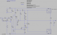
The simulator says the LTP Q1 & Q2 emitter currents are 1.994 and 2.019 mA. As you can see, in addition to fixing the LTP values, I added a biasing transistor. This is adjustable through R10 which is supposed to be a 5k or 10k trim-pot. I couldn't find a model for a trim pot in the simulator, though. All of the blank space is there because I'm presently working on... er, I mean hacking in the limiter circuit. So here is how this amp is looking now:
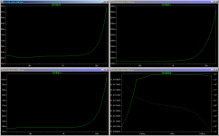
As you can see, the distortion is greatly reduced, and even the frequency response is improved. All for the cost of peanuts. It's still not exactly audiophile quality, but it's lookin' a little better.
R11 is in this circuit because I'm readying it for a limiter, and need to raise the output impedance of the Q3 driver. I've already got a limiter working, sort of, but not ready to post it just yet. What I'm finding out is that there is no such thing as an ideal limiter. It seems to be a compromise between distortion and protection. If you get some of one, then you give up the other.

The simulator says the LTP Q1 & Q2 emitter currents are 1.994 and 2.019 mA. As you can see, in addition to fixing the LTP values, I added a biasing transistor. This is adjustable through R10 which is supposed to be a 5k or 10k trim-pot. I couldn't find a model for a trim pot in the simulator, though. All of the blank space is there because I'm presently working on... er, I mean hacking in the limiter circuit. So here is how this amp is looking now:

As you can see, the distortion is greatly reduced, and even the frequency response is improved. All for the cost of peanuts. It's still not exactly audiophile quality, but it's lookin' a little better.
R11 is in this circuit because I'm readying it for a limiter, and need to raise the output impedance of the Q3 driver. I've already got a limiter working, sort of, but not ready to post it just yet. What I'm finding out is that there is no such thing as an ideal limiter. It seems to be a compromise between distortion and protection. If you get some of one, then you give up the other.
My first cut was a conventional VI limiter with a current limit at around 6.25A. Not much to it, and like most amps that are protected this way, I don't think it's very effective. Here's the schematic:
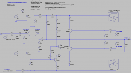
I put the simulated LTP emitter currents on the schematic as well as the bias currents and output offset voltage. The simulation shows that the maximum amp output is as follows:
So from the simulation it looks like the VI limiter is kicking in at 80-Watts with a 4-Ohm load. That's right on the edge of the SOA for the transistors. It's pretty clear that with greater loads, the TIP142/147 are operating outside of their SOA. Using conventional VI limiting, there is no way I can set a totally safe protection current and still have the amp drive 4-Ohm loads with the advertised power. It's easier to drive 8-Ohm loads with more power than 4-Ohm loads. And below 4-Ohms, it's a fish fry.
So I came up with a solution, an enhanced VI limiter which uses the Ic-to-Vbe non-linearity to apply more limiting as the the voltage between the rail and Vout gets larger. (Larger voltage usually indicates lower load impedance.) Q5 & Q7 networks in the schematic below are used to do this:
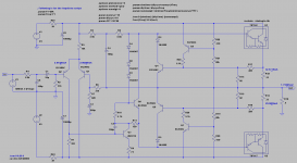
So here is the relevant data from the simulation:
A huge improvement over the conventional VI limiter. So that's how it works in theory. Yes, I know -- but in practice we find... So the next step is to build it and see how it works in the real world.
I've been working on this concept for a while. At first I tried to gate the bases of the VI limiter transistors. That approach added too much distortion and I couldn't get it to be non-linear enough.
What do y'all think of this little enhanced VI limiter invention?

I put the simulated LTP emitter currents on the schematic as well as the bias currents and output offset voltage. The simulation shows that the maximum amp output is as follows:
Code:
[FONT=Courier New][U]Ohms  Watts  %THD    Ic at  Vce     [/U]
8     123    0.254   5.55    2.75
4      80    0.919   6.30   21.8
3      --     --     6.34   27.9
2      --     --     6.33   34.2
1      --     --     6.33   40.5
0.5    --     --     6.34   43.6
[/FONT]
So from the simulation it looks like the VI limiter is kicking in at 80-Watts with a 4-Ohm load. That's right on the edge of the SOA for the transistors. It's pretty clear that with greater loads, the TIP142/147 are operating outside of their SOA. Using conventional VI limiting, there is no way I can set a totally safe protection current and still have the amp drive 4-Ohm loads with the advertised power. It's easier to drive 8-Ohm loads with more power than 4-Ohm loads. And below 4-Ohms, it's a fish fry.
So I came up with a solution, an enhanced VI limiter which uses the Ic-to-Vbe non-linearity to apply more limiting as the the voltage between the rail and Vout gets larger. (Larger voltage usually indicates lower load impedance.) Q5 & Q7 networks in the schematic below are used to do this:

So here is the relevant data from the simulation:
Code:
[FONT=Courier New][U]Ohms  Watts  %THD    Ic at  Vce     [/U]
8     122    0.211   5.56    2.45
4     118    0.660   7.66   15.6
3      --     --     2.50   40.7
2      --     --     2.08   44.0
1      --     --     1.77   46.6
0.5    --     --     1.65   47.7
[/FONT]
A huge improvement over the conventional VI limiter. So that's how it works in theory. Yes, I know -- but in practice we find... So the next step is to build it and see how it works in the real world.
I've been working on this concept for a while. At first I tried to gate the bases of the VI limiter transistors. That approach added too much distortion and I couldn't get it to be non-linear enough.
What do y'all think of this little enhanced VI limiter invention?
In your first diagram with R17/R14 monitoring the Vdrop of R12 you have a current limiter.
You can convert the I limiter to IV limiter by adding a resistor from +ve rail to junction of R17&R14
If you look at Leach, he has implemented the same I limiter.
Jens' Leach clone has the added resistor for IV limiter.
Your enhanced limiter use two extra resistors and an extra transistor that can be done without.
Have a think about adding an RC time constant so that the limiter is capable of passing short and medium term transient currents that exceed the DC limited current that you presently have, i.e. use some of the 100ms and 1ms and 100us SOA capability of the output devices without increasing the DC capability.
Last edited:
Thanks for the clarification, Andrew. I stand corrected. It is strictly a current limiter and behaves as such per the table. I played with the VI limiter but couldn't get it's performance much improved over the I limiter... maybe a cut of an Amp or so in the I limit. This is not enough. To keep the darlingtons in their SOA, you need to cut the limit by 4 amps. When I did that, it impacted normal load performance.
Can you please point me at some equations that would help me select the values of the 3 resistors in the VI limiter? I would like to play with that some more.
Thanks.
Can you please point me at some equations that would help me select the values of the 3 resistors in the VI limiter? I would like to play with that some more.
Thanks.
As I have said many times before, particularly in the leach clone thread, one needs the full model of the PSU and the Output stage to design all the component values for the DC IV limiter. This is not a trivial exercise.
Then one needs to ad in the transient pass limiter RC and finally the way to test that the models have properly predicted the actual performance. It's this last bit I have not done.
Then one needs to ad in the transient pass limiter RC and finally the way to test that the models have properly predicted the actual performance. It's this last bit I have not done.
while you are mooving on the right track you are missing one point ... the behaviour of darligtons ( if taking as a fact that the make is absolutelly close to specs )
if a darligton in your amp is warmer than the other will contuct more or less than the other ... now include that the driver of the specific transitor will also contact more and so on an thermal run away is arround the conrer
one will ask or say that almost the same with any transistor amplifier that has both drivers and outputs mounted on the same heatsink ....well not true ...darligtons by nature will behave worst ...
more or less same things happen in the input of the driver of the darligton ....
As I have said many times before, particularly in the leach clone thread, one needs the full model of the PSU and the Output stage to design all the component values for the DC IV limiter.
That almost sounds like people are depending on their PSU limitations to help protect their power amp. This is a valid practical approach, and I've seen it done before.
Ideally, we should only need to know the rail voltage. This would greatly simplify the math. Any PSU sag would only help keep the transistors within their SOA.
Searching the forums for "Jens' Leach clone" didn't yield anything specific. I even googled for Leach's Lo Tim paper and came up empty-handed. Have you got a link for me?
Thanks.
again you are in the right track .... many consumer amplifiers are designed this way and marginal trafos will serve as virtual protect of the amplifier ...of course expect distortion figures to hit the sky ..
musical fidelity , nad and audiolab done this in many models and yet again one may think that these amps are not designed to to work for party animals .
the other school says keep trafos and psu big ....keep cooling also big ...keep plenty and good transistors and will be happy ... though darligtons are out of this story ...
Sakis, you make a good point about thermal issues related to darlingtons. I have not done any sort of thermal analysis, but this could be a problem.
Heck, let's blow up a few! OK, maybe I'll increase the emitter resistors just a bit.
On another topic, I don't think this amp has any feedback stability issues. Here is the open loop gain analysis of the original Cheap150.
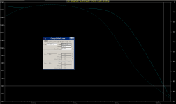
Open loop unity gain has a phase margin of almost 100 degrees. So maybe your only issue with this amp is potential thermal instability. That obviously depends on the cooling, and it should be possible to design around that problem.
BTW, Using the PSU sag to protect the power transistors is common practice in instrument amps.
Heck, let's blow up a few!
On another topic, I don't think this amp has any feedback stability issues. Here is the open loop gain analysis of the original Cheap150.

Open loop unity gain has a phase margin of almost 100 degrees. So maybe your only issue with this amp is potential thermal instability. That obviously depends on the cooling, and it should be possible to design around that problem.
BTW, Using the PSU sag to protect the power transistors is common practice in instrument amps.
Can you please point me at some equations that would help me select the values of the 3 resistors in the VI limiter? I would like to play with that some more.
This any good?
Brian
http://www.diyaudio.com/forums/grou...mp-pcb-group-buy-interest-64.html#post2364365
- Status
- This old topic is closed. If you want to reopen this topic, contact a moderator using the "Report Post" button.
- Home
- Amplifiers
- Solid State
- Cheap 100 to 150 Watt Amp