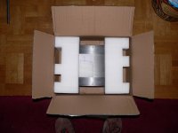
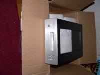
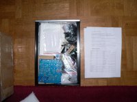
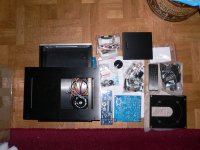
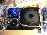
Hifidiy did send the cdprokit on 16th of october and I received it on the 19th ! Here are some pictures from the heavy weight chassis and it's parts.
Now i have to order a Cdpro Drive VAU1254 CD-PRO2LF.
Now i have to order a Cdpro Drive VAU1254 CD-PRO2LF.
Attachments
Looks good! Is the digital out taken from the cdmpro2? Or is it processed like these guys do?
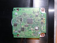
digital out for Cd-Pro2LF
digital out for Cd-Pro2LF
In the description of the kit it says:
"With special customized HIFIDIY 1PPM TCXO crystal and have extra one clock output interfaces to prepare for the replacement of CDPRO board when the use of crystal."
Difficult to understand what this actually mean, but my interpretation is that the signal is re-clocked in some way and that the clock can be connected also as master clock for the CDPRO.
I'm still waiting for my unit......
My unit arrived at the danish customs. I will probaply have to pay some custom + VAT fees
Anyway, in the description of the unit it says that there is a clock output which can be used to replace the "master" clock on the CD-Pro2 module.
Does somebody have any specific instructions on how to do this?
Maybe the "hifydiy.net" vendor could clarify this issue!
Great service so far Recommended.
Nic
Anyway, in the description of the unit it says that there is a clock output which can be used to replace the "master" clock on the CD-Pro2 module.
Does somebody have any specific instructions on how to do this?
Maybe the "hifydiy.net" vendor could clarify this issue!
Great service so far
Recommended.Nic
Okay, my turn
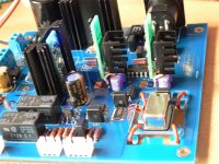
I assembled the remote and the displayboard. The instructions for the display were ment for another type of display but it was easy using the pictures on the Hifidiy site. The delivered parts are of a Xcellent quality: Oscon, Wima, Nichicon Muze + KG + KZ,Dale, etc.
-The 5V and 9V for the Cdpro unit are made by 2x2 lm317's(U8/U18 x U19/U21). 9V stays untouched, but the 5V stage is used for several other regulators,etc. Before the first lm317(U8) power (12V) is used for the two relais who switch the 5V+ 9V. After U8 power (8V)is used for U4/U6/U22. After the next LM317 U18 (5V) it goes to the Cdpro.
- U4 /U6/U22 are LM1117 regulators, which are standard regs. U4 powers the Crystal (16.9344MHZ), and 2x 74hc04. U6 powers the optical out and a 78cf09m. U22 powers partly the display.
I don't know if it is really necessary, this is the chassis and not the DAC and the quality of the kit is good, but I'm going to change the supply with shuntregs. Finally I can do that, I stared long enough at the insides of my expensive Rega Apollo ans Saturn and wondered why all those cheap electronic parts have to result in such a darn expensive product. Boombox control IC's, everywhere 7805's. No seperate powerstages, The stage for the (lm317)IVY powers also the analog 7805
and digital supply for the Wolfson DAC. Enough.
I'm not gonna use The 9V stage but build it with a TP placid shunt.
I leave U8 were it is, so it can power U4/U6/U22, but will not use U18.
I'm using another placid (at 5V) to power the CDpro directly.I want to use two
New class D shunts for U4 and U6.
The 9V for the cdpro has a max load of 200mA and a peak of 700mA
The 5V has a max load of 300mA, this to adjust the placid's. Is the 9V for the spindle and should I adjust at 700MA ?
Cheers, Erik.
Last edited:
Hi Erik,
Seems that you, like me, are thinking about tweaking the unit even before putting it together. I have gone quite carefully over the schematics (which are send by e-mail when the unit has been paid/shipped) and I have similar plans to yours with respect to upgrading the power supplies.
As I don't have the unit in my hands yet (in transit from Denmark -> Italy) I have a few questions:
1) What voltages does pins 1,2 and 3 on the R36 connector supply to the display board? I cannot really understand the power circuit following secondaries J2 and J3.
2) What voltage is used to control the power relays via connector J6 from the display board?
3) do you know if the extra xtal output can be used to "replace" the master clock on the transport?
One great thing about the CD-Pro2M/LF is that it output also PCM data and that the format (I2S, EIAJ etc.) can be selected via the transports DSA software interface. This is not utilized/implemented in this kit. I have contacted hifidiy.com but they have not been very helpful in this respect. There are several suppliers of control units for the CD-Pro2 and I'm considering if it would be possible to replace the entire control/display circuitry with something more versatile.
Cheers,
Nic
Seems that you, like me, are thinking about tweaking the unit even before putting it together. I have gone quite carefully over the schematics (which are send by e-mail when the unit has been paid/shipped) and I have similar plans to yours with respect to upgrading the power supplies.
I thinking along this line too, but I will use a high quality series regulator here as a shunt rated 700 mA would have to dissipate a lot of heat when rated for 700 mA, but running at 200 mA most of the time.I'm not gonna use The 9V stage but build it with a TP placid shunt.
I will replace the U18 (and its circuitry) with a 5V shunt reg. I will not feed this directly to the transport as I kind of like the relay controlled startup powering sequence.I leave U8 were it is, so it can power U4/U6/U22, but will not use U18. I'm using another placid (at 5V) to power the CDpro directly.
I agree, low power HQ shunts for these circuits. Not important for U22.I want to use two New class D shunts for U4 and U6.
I'm not sure. Maybe a shunt reg rated @ 300 mA can take the 700mA transients (disk spin-up) without problems. Can you read the ratings of the different secondaries on the transformer?The 9V for the cdpro has a max load of 200mA and a peak of 700mA
The 5V has a max load of 300mA, this to adjust the placid's. Is the 9V for the spindle and should I adjust at 700MA ?
As I don't have the unit in my hands yet (in transit from Denmark -> Italy) I have a few questions:
1) What voltages does pins 1,2 and 3 on the R36 connector supply to the display board? I cannot really understand the power circuit following secondaries J2 and J3.
2) What voltage is used to control the power relays via connector J6 from the display board?
3) do you know if the extra xtal output can be used to "replace" the master clock on the transport?
One great thing about the CD-Pro2M/LF is that it output also PCM data and that the format (I2S, EIAJ etc.) can be selected via the transports DSA software interface. This is not utilized/implemented in this kit. I have contacted hifidiy.com but they have not been very helpful in this respect. There are several suppliers of control units for the CD-Pro2 and I'm considering if it would be possible to replace the entire control/display circuitry with something more versatile.
Cheers,
Nic
Hi Nic,
Quote :
"Power supply for the CD-PRO2LF
The power supply for the CD-PRO2LF consists of a positive 9V supply and a positive 5V supply. Both make use of the same ground and both are rated below 1 Ampere. The 9V supply is mainly used to drive the motors and the actuators in the system. Therefore the required accuracy of the level is not important, the handling of pulses is however important. The 5V supply is mainly used for the operation of the servo and decoder section. Internally on the PCB this voltage is brought once more down to 3.3V for the digital section. The consequence of this 3.3V is however that an external clock should be inserted as well with a maximum of 3.3V and that one can expect only 3.3V levels of the signals coming from IC pins. Cl16 is such a signal as also the signal used by the Tentlabs XO3 board for re-clocking the digital output. Both the 9V and the 5V have an influence on the analogue audio section of the CD-PRO2LF. If you want to use this output direct then it is advised to make a well stabilized and responsive 9V and a well stabilized and responsive 5V section.
Both voltages should be available at nearly the same time when switched on. Therefore they should be loaded with about the same buffering capacitance. Unlike in the past the timing of the power supply is no longer critical."
-It seems that the 9V is not that important, may just use the onboard supply ? What is stated about the external clock is abacadabra for me (yet).
-The toroid will feed the placid for the 5V to the relay and the same AC voltage will feed U8.
- I did read that the regulator 3V3 for the digital supply on the cdpro is also a lm1117. It's not clear for me what is used for the CDpro and what for the onboard DAC.
As I don't have the unit in my hands yet (in transit from Denmark -> Italy) I have a few questions:
1) What voltages does pins 1,2 and 3 on the R36 connector supply to the display board? I cannot really understand the power circuit following secondaries J2 and J3.
-pin1+2 =AC3.3V to power the display,pin3 is "Vee" powers the display driverchip.
2) What voltage is used to control the power relays via connector J6 from the display board?
-They are powered by 12V and switched by the eeprom on the displayboard, called 5 and 9 (?)
3) do you know if the extra xtal output can be used to "replace" the master clock on the transport?
- see the quote + External clock oscillator
One great thing about the CD-Pro2M/LF is that it output also PCM data and that the format (I2S, EIAJ etc.) can be selected via the transports DSA software interface. This is not utilized/implemented in this kit. I have contacted hifidiy.com but they have not been very helpful in this respect. There are several suppliers of control units for the CD-Pro2 and I'm considering if it would be possible to replace the entire control/display circuitry with something more versatile.
-LOL almost all the money for a beautiful case
"Almost" sleeping time. Currents for toroid : 3.3V(1A) 20V(0.1A) 9V(1A) 12V(1.50A) 12V(1.50A)
Last edited:
Thanks (I already got it - but anyway).
It looks like it might be worthwhile changing the onboard LM1117 3V3 supply on the transport with a good shunt type. It feeds the SAA7324 DAC chip (that draw around 20 mA). I will have to figure what else is feed by this supply (the xtal + ??). The laser controller (TZA1022) seems to run of 5V.
Maybe I will be able to destroy it all before even listening to it in its base configuration!!!
Nic
Hi NIc,
They are all the same type, series shunt(I believe):
NewClassD UWB Regulators
Dexa Semiconductor regulators
I'm also using this reg on the 9V supply. A "Placid" didn't fit and runs hot at 700mA. This is also the easy way, placed instead of the second lm317(U21)
I hope TP soon brings out the new buff32 because I don't have a DAC to test.
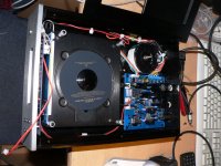
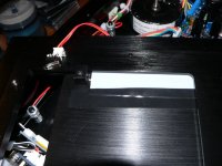
The rubber rings on the crystalplatform are to be used for mounting the cdpro. If anyone wants to build this chassis, be careful, measure everything !
This because the supplied building instructions are rather poor or meant for something else, I got most things from photo's.
They are all the same type, series shunt(I believe):
NewClassD UWB Regulators
Dexa Semiconductor regulators
I'm also using this reg on the 9V supply. A "Placid" didn't fit and runs hot at 700mA. This is also the easy way, placed instead of the second lm317(U21)
I hope TP soon brings out the new buff32 because I don't have a DAC to test.
The rubber rings on the crystalplatform are to be used for mounting the cdpro. If anyone wants to build this chassis, be careful, measure everything !This because the supplied building instructions are rather poor or meant for something else, I got most things from photo's.
Congratulations!!!
Did you close it up? How does the top lid mechanism function?
Now you just need a DAC, the buffalo is as great as their times of getting new version for sale.....
The unit "only" have digital output (SPDIF, EBU and Toslink). Have you been able to test the sonics in some way? There are also analog out headers on the CDPRO so you could connect these to your pre/power amp.
My assembly will take a bit longer as I hope to build in an EIAJ based NOS DAC for HQ analog output. Also I have some plans for replacing the L1117 3.3V reg and xtal on the CDPRO. I will be back with my progress.
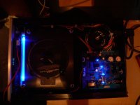
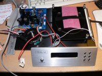
Yes it's finished !, my studyroom is a total mess. I'm adding a picture from the top mechanism, fully manually controlled
The sound is very good ( coming from my pc speakers), can't wait for that new Buff32 to come out. Which output should I use to connect the cdpro to the Buffalo ? SPDIF, EBU or Toslink ? Haven't got the knowledge about that yet.
Regards, Erik.
The sound is very good ( coming from my pc speakers), can't wait for that new Buff32 to come out. Which output should I use to connect the cdpro to the Buffalo ? SPDIF, EBU or Toslink ? Haven't got the knowledge about that yet.
Regards, Erik.
Attachments
- Status
- This old topic is closed. If you want to reopen this topic, contact a moderator using the "Report Post" button.
- Home
- Source & Line
- Digital Source
- Chassis for CD-Pro2 transport