Tubes conduct heat by radiation as such if you move the small tubes away from the big hot tubes they will be heated less by them. This results in less need for holes and if you space them apart a little you can use pearl cooler or the like to keep them cool as well as shield them from outside noise sources . The last point may be a bit controversial as to effect but it will help to stop RF and light (direct sun light) from the small signal tubes. Glass tubes larger than the power tubes look nice and can produce a chimney effect increasing air flow and cooling. forced air by a small computer fan slowed down to be very quiet is allso a thought. Good luck with this .
Last edited:

Ahhhh... I get it. I thought that the transformers were going to be on top of the top plate (I probably read it wrong or pictured it differently).
Rundmaus, well this is your lucky day, I am not that busy at work right now and I am full of ideas and quite opinionated today (I hope you can appreciate that work related boredom drives me to diyaudio).
Why are you hanging your transformers upside down? I realize maybe for ease of access and lift off top plate and BINGO! it is all there without any wires restricting movement, but why not place the power transformer across a plate/bracket/square tube/angle on the bottom? Or even mounted on a plate attached to the back of the chassis?
It will relieve stress to the top plate significantly (that is at least 20 kilograms for the all the transformers shown in the picture?). You can use screw in posts or jacks to connect or disconnect the wiring to the top plate's components. Just saying again, as an option.
And the heat will be an issue. You might be better off just with a small opening louvered or open as mesh to clear out any excess heat in the chassis. And keep the cutout for the tubes.
Last edited:
Have you considered monoblocks?
It would be less strain on the top plate and your are already dealing with, as you said, 2x EL34 power tubes, 2x ECC88 drivers plus 1x EF184 CCS per side/channel, 2x GZ34 rectifiers for the B+, and 1x EZ81 for B-. You can always make add one more EX81 to the other side's B-. Other than more side panels and a redesign, maybe this will solve the weight on the top plate issue and you can still have cut outs.
Just saying...
Good Idea.IMHO.
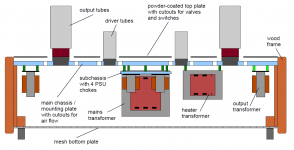
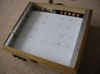
I forgot to mention two holes for adjust negative bias of output valves.
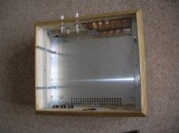
It's all homemade, chassis, knobs, PCBs, transformers, etc...
The chassis is made of anodized aluminium C-shaped plates, the bottom plate is perforated iron, attached with aluminium brackets.
The whole chassis is a Faraday cage, wood is only ornamental.
Attachments
Last edited:
Hummmmmmmmmmmmmmm,
Power Tx by the driver tubes?
The power supply seems to be spread across the top plate..
Why don't you hinge the mounting plate and fix the bottom plate and mount the transformers on the bottom?
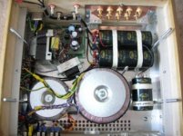
This is what I did with my OTL..Pic (Sorry for reposting photos its only way I can show you)
the aluminium is 3mm supported with angle using wooden sides..I have 2 toroid and one standard Tx plus chokes all on the bottom plate..
Middle plate acts as a shield and also holds the wire and components.. If your only running EL34..you could build standard..the heat should not be an issue..
The Mod from the pic was to remove the aluminium all along the top plate and just use supports. (reduced heat transfer from top plate to amp support plate)
For EL34 it should be a lot easier.. I used metal self tapping screws into the wood to hold the aluminium angle they cannot be seen outside the chassis.
Regards
M. Gregg
Power Tx by the driver tubes?
The power supply seems to be spread across the top plate..
Why don't you hinge the mounting plate and fix the bottom plate and mount the transformers on the bottom?
This is what I did with my OTL..Pic (Sorry for reposting photos its only way I can show you)
the aluminium is 3mm supported with angle using wooden sides..I have 2 toroid and one standard Tx plus chokes all on the bottom plate..
Middle plate acts as a shield and also holds the wire and components.. If your only running EL34..you could build standard..the heat should not be an issue..
The Mod from the pic was to remove the aluminium all along the top plate and just use supports. (reduced heat transfer from top plate to amp support plate)
For EL34 it should be a lot easier.. I used metal self tapping screws into the wood to hold the aluminium angle they cannot be seen outside the chassis.
Regards
M. Gregg
Attachments
Last edited:
Why are you hanging your transformers upside down? I realize maybe for ease of access and lift off top plate and BINGO! it is all there without any wires restricting movement, but why not place the power transformer across a plate/bracket/square tube/angle on the bottom? Or even mounted on a plate attached to the back of the chassis?
I'd use a piece of aluminum U-channel or angle for this. I have some aluminum U-channel that's 1/8" thick, 1" wide, and 1/2" tall (3.2, 25.4, 6.3 mm respectively). That's stout stuff. Some of it I actually bought because I intended to make a chassis with a perforated sheet as top plate and needed some structural support below the transformers.
I like the idea of using perf plate for the top plate. Look at how SY has done it on his amps. That gives you RF shielding plus ventilation. If you use a template made from solid sheet (say 1.6 mm aluminum) for the holes, it's actually pretty easy to get the holes where you want them in the perf plate.
Good luck with your dissertation (and amp project).
~Tom
M Gregg, my goodness... THAT is some awesome cable management -- where did you learn it and how many hours did that take you? Makes my very simple light sabre build (lights up, has a speaker, and and makes an oscillating sound housed in brass fittings) for my son look like rat's nest.
But to drag this back onto topic, did you consecutively map both the bottom plate with the top plate for the hole placement? Or did you have a top plate and measured and adjusted afterwards?
I am asking because of the large sockets (I am guessing 6C33) can be mapped easily enough to the bottom, but the gain tubes with the separate plate in your picture? Those must have been trickier.
Hi Rundmaus, I wondered where the holes for the transformer wires were in your top cover (on the other thread). The view you posted here doesn't show how far back the power transformer is from your drivers - might be part of the concern expressed about the power transformer being "close" to the driver tubes.
Putting the power transformer inside will add to the internal heat of the amplifier, any idea how heavily the power transformer is loaded in your design? From what I remember of your top-plate design, you've got lots of ventilation holes and slots.
Putting the power transformer inside will add to the internal heat of the amplifier, any idea how heavily the power transformer is loaded in your design? From what I remember of your top-plate design, you've got lots of ventilation holes and slots.
I don't want to drag the thread away from Rundmaus build.
Quote did you consecutively map both the bottom plate with the top plate for the hole placement? Or did you have a top plate and measured and adjusted afterwards?
I laid the components out on cardboard to get the smallest size I could then cut the metal. I put the top plate and the amp plate on top of each other.
Then drilled the locating holes for the all thread. Then marked out and drilled a pilot hole for the centers of the pre/driver and 6C33C's..Then cut the PCB and placed it under the bottom plate and drilled the pilot holes into the PCB. Then drilled the mounting holes in the PCB and lined up the PCB pilot tube holes and drilled the chassis from the PCB mounting holes, then built the PCB.
Wiring= engineer..It took a while..
So back to the topic...
Regards
M. Gregg
Attachments
Last edited:
Hey there,
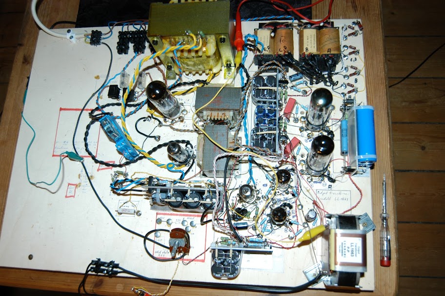
Ah, I understand your concerns regarding the power transformer placement. The simplified side view does not show everything. In fact, the power transformer is as far from the driver circuitry as possible.
I posted a picture of the (working) test setup in another thread, one channel is build to scale there, with simply everything on top of the plate. That should make more clear what I am planning, see:
http://www.diyaudio.com/forums/tubes-valves/221110-locating-hum-source-4.html#post3433193
Regards,
Rundmaus
Picture:
Hummmmmmmmmmmmmmm,
Power Tx by the driver tubes? The power supply seems to be spread across the top plate..
The view you posted here doesn't show how far back the power transformer is from your drivers - might be part of the concern expressed about the power transformer being "close" to the driver tubes.
Ah, I understand your concerns regarding the power transformer placement. The simplified side view does not show everything. In fact, the power transformer is as far from the driver circuitry as possible.
I posted a picture of the (working) test setup in another thread, one channel is build to scale there, with simply everything on top of the plate. That should make more clear what I am planning, see:
http://www.diyaudio.com/forums/tubes-valves/221110-locating-hum-source-4.html#post3433193
Regards,
Rundmaus
Picture:
No, no, no... I didn't want to drag it away from Rundmaus either, but saw it as an opportunity for everyone here including Rundmaus to see what can be done and how it can be done.
It is interesting because your build dispenses with the whole of the cutouts that Rundmaus has (since the tubes are mounted below the surface of the top plate) and the top plate becomes more cosmetic than structural instead.
Your top plate has the holes for the tubes slightly larger than the tubes? How far up the tubes does the top plate sit? Near the tube sockets or further?
All good ideas for Rundmaus (with the large variety and tube complement of Rundmaus'... I'm still with monoblocks for structure and bigger holes if that works for him).
The top plate,
is about 10mm from the tube bases on the Power tubes..The pre tube bases sit just below the top plate about 3-4mm.
The gain with putting the TX's under the amp plate is it compacts the design. The Air is drawn from the front of the chassis through the holes as shown..then travels across the power transformers etc and is drawn up into the top plate at the back<<the amp support plate is not all the way across the chassis (front to back) so air flow takes the form of a sidways "U". the shield for the Pre-amp is supported just off the chassis and is about 2mm from the top plate.
There are two 20mm holes under the PCB to allow cool air from the vent holes in the bottom, so the preamp tubes get cool air and vents through the top plate via the tube holes.
The Power tubes draw the air through the amp...any hot components are used to help drive the flow so are placed to drive up to the power tubes.
Tube amps can be big..so I think the trick is to get it as small and functional as possible. And still keep it cool..
Regards
M. Gregg
Rundmaus,
I see why you are designing the way you are...the layout is very important..(Looking at the thread you linked to)
Its great that you have it working as a test piece. It might be difficult to compact the design without further work on the layout..
Regards
M. Gregg
I see why you are designing the way you are...the layout is very important..(Looking at the thread you linked to)
Its great that you have it working as a test piece. It might be difficult to compact the design without further work on the layout..
Regards
M. Gregg
M. Gregg,
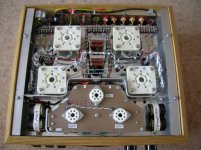
did the photo disperse your concerns with the power supply layout? I'm not sure if everything is visible clear enough.
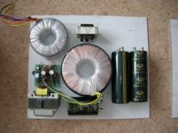
Back end of chassis, in the middle, main power transformer. In front, chokes and rectifiers for one channel. Right of the chokes, 1st and 2nd C filters, supplying output stage. Right next to them, output stage with the cathode resistors and bypass caps on the right edge of the chassis.
In front of the chokes, RC filtering for negative rail, right of it CCS and driver stage. In front of the driver stage, 3rd C filter supplying driver stage. Front right corner is the output transformer.
The relay on the left side of the test board turns the B- rectifier on as soon as the B+ rail reaches approx. 80% of design value.
Rundmaus
did the photo disperse your concerns with the power supply layout? I'm not sure if everything is visible clear enough.
Back end of chassis, in the middle, main power transformer. In front, chokes and rectifiers for one channel. Right of the chokes, 1st and 2nd C filters, supplying output stage. Right next to them, output stage with the cathode resistors and bypass caps on the right edge of the chassis.
In front of the chokes, RC filtering for negative rail, right of it CCS and driver stage. In front of the driver stage, 3rd C filter supplying driver stage. Front right corner is the output transformer.
The relay on the left side of the test board turns the B- rectifier on as soon as the B+ rail reaches approx. 80% of design value.
Rundmaus
At the end of the day,
If the layout works on the test piece it should work on the build, however in most cases you will find that once built you may have other concerns..
Could I have done it differently..my advice such that it is, would be to position the parts exactly as you expect them to be on the amp and test it again..just to be sure. Its never good to spend hours of work and find you have a problem. The flux from the Tx's might be different when inverted (It might be OK..) So it might be an idea to lift the board with some blocks and reposition and test again.
Regards
M. Gregg
my advice such that it is, would be to position the parts exactly as you expect them to be on the amp and test it again..[...] The flux from the Tx's might be different when inverted (It might be OK..)
Yes, the original plan was to position everything exactly as it will be in the final build. But it was somewhat simpler to do it as shown in the picture, I have to admit
However, the only thing that's different from the final layout is the tubes, which will be sticking out on the other side instead of being crammed between all the other stuff. I have some hope that this will make the situation better instead of worse...
Rundmaus
You may find very thick aluminium can tend to be "Not very flat"...
Well, I am planning to order the plates from a front panel service, they guarantee a basic flatness. I'm not sure if 5mm is needed or if 4mm will suffice, I think I'll ask the guys in our mechanical workshop at the university. They probably have the right formula to calculate the bending of a rectangular plate supported at the edges under a certain load.
The 'cosmetic' top plate will be thinner, 1mm or 2mm should suffice there, as it has nothing to do but to look nice
Rundmaus
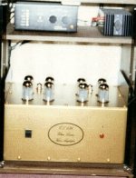
This is another just for interest,
Again the top plate is just for looks, the amp is all aluminium plate with aluminium angle chassis. 8X EL34/kt66/6L6/ triode, pentode, UL switched.
The tubes were mounted on hard wire PCB's and again it was split with an amp plate and air flow was from bottom back to top..Gold anodised..
The side plates were higher than the tubes to protect cabinets from heat..and protect tubes..just another example..this used tube to space the plates with all thread.
Built some years ago.. The big mistake with this amp was it had no master volume control so you needed a passive pre..relay switched inputs.. it was also a bit on the loud side..audio note caps etc..carbon resistors.
I should add that the top plate is not thin perhaps 2.5mm or it can give microphonics..
Regards
M. Gregg
Attachments
Last edited:
- Status
- This old topic is closed. If you want to reopen this topic, contact a moderator using the "Report Post" button.
- Home
- Amplifiers
- Tubes / Valves
- Chassis design question / cooling of small signal valves