Hi all. Not sure if something like this has been discussed - my search did not turn up anything.
I have a Mingda (a chinese brand) integrated tube amplifier, and I want to convert it to a power amp. Besides getting rid of the volume control part, I guess I should also bypass its preamp part, but I am not sure how to do that. The integrated amp uses 2 12ax7 as input, two 6sn7 as the driver and 4 KT88 as outputs. I don't think I can just connect the output of a preamp to the two 6sn7. Any advices?
Thank you,
Frank
f1802llk said:Hi all. Not sure if something like this has been discussed - my search did not turn up anything.
I have a Mingda (a chinese brand) integrated tube amplifier, and I want to convert it to a power amp. Besides getting rid of the volume control part, I guess I should also bypass its preamp part, but I am not sure how to do that. The integrated amp uses 2 12ax7 as input, two 6sn7 as the driver and 4 KT88 as outputs. I don't think I can just connect the output of a preamp to the two 6sn7. Any advices?
Thank you,
Frank
Find and post the schematic and we will be able to answer.. Mostly likely the 12AX7 is in the first stage of the power amplifier and will be retained.
Probably at its simplest you can find the connections to each channel's volume control pot wiper, disconnect and run each to the appropriate channel RCA input jack. (Remove old connection to center pin first though) Place a 100K resistor across each jack to assure that the inputs have a path for input stage grid current.
Thank you for your reply. I did try removing only the volume control and have the signal from RCA going directly to the grid of the input tube. It works fine but has too much gain.
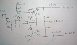
I drew up a schema for the input and driver sections of the amp. It is what my amp is now after quite a few mods. It's attached as a picture. I am not sure if I made it clear in the picture: the two halves of 12AX7 are connected together, so the two grids (7 and 2) are connected by a wire, so are the two cathodes (8 and 3), etc.
Thank you.
Frank
Attachments
Yeah, no flexibility to make minor changes, what I would recommend is using a resistive attenuator at the input. Use a 68K (from signal) and 33K (to ground) in series, take output between the two and you will have ~10dB less gain and an input impedance about 100K. Other ratios are possible for example 2 x 49.9K gives you 6dB attenuation with 100K input Z.. If you are using a lower impedance source, try halving the recommended values for a 50K input impedance as this will reduce the interaction with the 12AX7's miller capacitance, possibly resulting in slightly better HF response. Going beyond this requires you to redesign the front end circuitry.
There is no NFB, and it's push-pull with triode. Thanks for suggesting 12AY7. I'll give them a try.
I am not afraid to change some circuitry though. I guess I can also lower the gain a bit by lowering the anode resistor from 100k to 47k (lower the B+ accordingly from 288v to about 200v), and lower the next stage grid resistor from 1M to 470K, right? Would these be a sensible thing to do? Another thing is that I could not figure out why they made use of 12AX7 that way. I mean why they wanted to connect the two halves together. I don't think this would affect the gain (voltage), just getting twice the current, right? One really need only one 12AX7 for the whole thing, one half for the left channel and the other for the right. Or I missed something here?
Frank
f1802llk said:From the datasheet for 12AY7, it has significantly more current than 12AX7. So I'd have to decrease the cathode resistors (currently they are 1.1k) and/or the anode resistor (currently 100k)?
Thank you,
Frank
Not necessarily, try it as is first, and then tweak if needed.
- Status
- This old topic is closed. If you want to reopen this topic, contact a moderator using the "Report Post" button.
- Home
- Amplifiers
- Tubes / Valves
- changing an integrated tube amp to a power amp